Sign In
Upload
Manuals
Brands
Panasonic Manuals
Plasma TV
TH-65PY700H
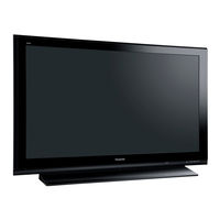
Panasonic TH-65PY700H 65-inch Plasma TV Manuals
Manuals and User Guides for Panasonic TH-65PY700H 65-inch Plasma TV. We have
1
Panasonic TH-65PY700H 65-inch Plasma TV manual available for free PDF download: Service Manual
Panasonic TH-65PY700H Service Manual (210 pages)
Brand:
Panasonic
| Category:
Plasma TV
| Size: 44.29 MB
Table of Contents
Audio Input RCA PIN Type
2
Packing Exploded Views
2
Table of Contents
3
Lead of Wiring
3
1 Applicable Signals
6
2 Safety Precautions
7
General Guidelines
7
Touch-Current Check
7
3 Prevention of Electrostatic Discharge (ESD) to Electrostatically Sensitive (ES) Devices
8
4 About Lead Free Solder (Pbf)
9
5 Service Hint
10
6 Plasma Panel Replacement Method
11
Remove the
11
Remove the P(P-1)-Board
11
Remove the P(P-2)-Board
11
Remove the Rear Terminal Cover
11
Remove the Tuner Unit
12
Remove the DH-Board
12
Remove the DG-Board
13
Remove the H-Board
13
Remove the JG-Board
13
Remove the PA-Board
14
Remove the D-Board
14
Remove the Speaker Box Assy (L, R)
15
Remove the SU-Board
15
Remove the SD-Board
15
Remove the SC-Board
16
Remove the SS2-Board
16
Remove the SS3-Board
16
Remove the SS-Board
16
Remove the Reinforcement Angles (L, R) and the Connection Plate (A, B, C, D)
17
Remove the Fan Unit (R) and Fan
17
Remove the Fan Unit (L) and Fans
18
Remove the Cabinet-Fixing Metal (A) (Upper)
18
Remove the Cabinet-Fixing Metal (B) (Upper)
18
Remove the C1-Board
18
Remove the C2-Board
18
Remove the C3-Board
19
Remove the Front Shield Metal
19
Remove the Tuner Support Metal
19
Remove the Support Metal (L)
19
Remove the Support Metal (R)
19
Remove the Cabinet-Fixing Metal (A) (Lower)
20
Remove the Cabinet-Fixing Metal (B)(Lower)
20
Remove the C4-Board
20
Remove the C5-Board
20
Remove the C6-Board
21
Remove the Front Bracket
21
Remove the G-Board
21
Remove the GS-Board
22
Remove the S-Board
22
Remove the K-Board
22
Remove the R-Board
22
Remove the J-Board
23
Remove the Plasma Panel Section from the Cabinet Assy (Glass)
23
Remove the Squawker Speaker
24
Replace the Plasma Panel (Finished)
24
7 Caution Statement
25
8 Location of Lead Wiring 8.1. Lead of Wiring
26
9 Self-Check Function
29
Check of the IIC Bus Lines
29
Power LED Blinking Timing Chart
30
No Power
31
No Picture
32
Local Screen Failure
33
10 Service Mode
34
How to Enter into Service Mode
34
Service Tool Mode
36
11 Adjustment Procedure
37
Driver Set-Up
37
Initialization Pulse Adjust
38
Printed Circuit Board) Exchange
38
Adjustment Volume Location
39
Test Point Location
39
12 Adjustment
40
Sub-Contrast Adjustment
40
PAL Panel White Balance Adjustment
41
HD White Balance Adjustment
42
13 Hotel Mode
43
14 Conductor Views
45
P(1)-Board
45
P(2)-Board
48
PA-Board
51
G-Board
52
H-Board
53
GH and GS-Board
55
JG-Board
56
DG-Board
58
DH-Board
61
D-Board
62
C1-Board
64
C2-Board
65
C3-Board
66
C4-Board
67
C5-Board
68
C6-Board
69
SC-Board
70
SU-Board
73
SD-Board
74
SS-Board
75
SS2 and SS3-Board
78
J,K,R and S-Board
79
15 Schematic and Block Diagram
81
Schematic Diagram Note
81
Main Block Diagram
82
P-Board (1 of 2) Block Diagram
83
P-Board (2 of 2) Block Diagram
84
P-Board (1 of 2) Schematic Diagram
85
P-Board (2 of 2) Schematic Diagram
86
PA-Board Block Diagram
87
PA-Board (1 of 2) Schematic Diagram
88
PA-Board (2 of 2) Schematic Diagram
89
G, and S-Board Schematic Diagram
90
H-Board (1 of 2) Block Diagram
91
H-Board (2 of 2) Block Diagram
92
H-Board (1 of 5) Schematic Diagram
93
H-Board (2 of 5) Schematic Diagram
94
H-Board (3 of 5) Schematic Diagram
95
H-Board (4 of 5) Schematic Diagram
96
H-Board (5 of 5) Schematic Diagram
97
GH-Board Schematic Diagram
98
GS-Board Block Diagram
99
GS-Board Schematic Diagram
100
JG-Board Block Diagram
101
JG-Board (1 of 5) Schematic Diagram
102
JG-Board (2 of 5) Schematic Diagram
103
JG-Board (3 of 5) Schematic Diagram
104
JG-Board (4 of 5) Schematic Diagram
105
JG-Board (5 of 5) Schematic Diagram
106
DG-Board (1 of 3) Block Diagram
107
DG-Board (2 of 3) Block Diagram
108
DG-Board (3 of 3) Block Diagram
109
DG-Board (1 of 12) Schematic Diagram
110
DG-Board (2 of 12) Schematic Diagram
111
DG-Board (3 of 12) Schematic Diagram
112
DG-Board (4 of 12) Schematic Diagram
113
DG-Board (5 of 12) Schematic Diagram
114
DG-Board (6 of 12) Schematic Diagram
115
DG-Board (7 of 12) Schematic Diagram
116
DG-Board (8 of 12) Schematic Diagram
117
DG-Board (9 of 12) Schematic Diagram
118
DG-Board (10 of 12) Schematic Diagram
119
DG-Board (11 of 12) Schematic Diagram
120
DG-Board (12 of 12) Schematic Diagram
121
DH-Board Block Diagram
122
DH-Board (1 of 4) Schematic Diagram
123
DH-Board (2 of 4) Schematic Diagram
124
DH-Board (3 of 4) Schematic Diagram
125
DH-Board (4 of 4) Schematic Diagram
126
D-Board (1 of 2) Block Diagram
127
D-Board (2 of 2) Block Diagram
128
D-Board (1 of 8) Schematic Diagram
129
D-Board (2 of 8) Schematic Diagram
130
D-Board (3 of 8) Schematic Diagram
131
D-Board (4 of 8) Schematic Diagram
132
D-Board (5 of 8) Schematic Diagram
133
D-Board (6 of 8) Schematic Diagram
134
D-Board (7 of 8) Schematic Diagram
135
D-Board (8 of 8) Schematic Diagram
136
C1, C2, C5 and C6-Board Block Diagram
137
C2, C3, C4 and C5-Board Block Diagram
138
C1-Board (1 of 2) Schematic Diagram
139
C1-Board (2 of 2) Schematic Diagram
140
C2-Board (1 of 2) Schematic Diagram
141
C2-Board (2 of 2) Schematic Diagram
142
C3-Board (1 of 2) Schematic Diagram
143
C3-Board (2 of 2) Schematic Diagram
144
C4-Board (1 of 2) Schematic Diagram
145
C4-Board (2 of 2) Schematic Diagram
146
C5-Board (1 of 2) Schematic Diagram
147
C5-Board (2 of 2) Schematic Diagram
148
C6-Board (1 of 2) Schematic Diagram
149
C6-Board (2 of 2) Schematic Diagram
150
SC-Board Block Diagram
151
SC-Board (1 of 4) Schematic Diagram
152
SC-Board (2 of 4) Schematic Diagram
153
SC-Board (3 of 4) Schematic Diagram
154
SC-Board (4 of 4) Schematic Diagram
155
SU and SD-Board Block Diagram
156
SU-Board (1 of 3) Schematic Diagram
157
SU-Board (2 of 3) Schematic Diagram
158
SU-Board (3 of 3) Schematic Diagram
159
SD-Board (1 of 3) Schematic Diagram
160
SD-Board (2 of 3) Schematic Diagram
161
SD-Board (3 of 3) Schematic Diagram
162
S, SS, SS2 and SS3-Board Block Diagram
163
SS-Board (1 of 2) Schematic Diagram
164
SS-Board (2 of 2), SS2 and SS3 Schematic Diagram
165
J,K and R-Board Schematic Diagram
166
16 Exploded Views & Replacement Parts List
167
Exploded Views
167
Fan Exploded Views
168
Accessory
169
Packing Exploded Views
170
Packing Exploded Views
172
Replacement Parts List Notes
173
Mechanical Replacement Parts List
174
Electrical Replacement Parts List
175
Advertisement
Advertisement
Related Products
PANASONIC Viera TH-65PY800P
PANASONIC TH-65PY700E
Panasonic TH-65PY700AZ
Panasonic TH-65PY700M
Panasonic TH-65PY700MR
Panasonic TH-65PY850D
Panasonic TH-65PY850H
Panasonic TH-65PY850M
Panasonic TH-65PY850MR
Panasonic Viera TH-65PZ850A
Panasonic Categories
Camcorder
Air Conditioner
TV
Digital Camera
Cordless Telephone
More Panasonic Manuals
Login
Sign In
OR
Sign in with Facebook
Sign in with Google
Upload manual
Upload from disk
Upload from URL