Sign In
Upload
Manuals
Brands
PIAGGIO Manuals
Engine
500 cc
PIAGGIO 500 cc Manuals
Manuals and User Guides for PIAGGIO 500 cc. We have
1
PIAGGIO 500 cc manual available for free PDF download: Service Manual
PIAGGIO 500 cc Service Manual (240 pages)
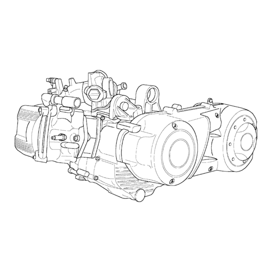
Engine 500 cc 4-stroke 4-valve
Brand:
PIAGGIO
| Category:
Engine
| Size: 44.7 MB
Table of Contents
Table of Contents
3
Safety Prescriptions
5
Maintenance Regulations
5
Spark Plug
7
Check and Replacement
7
Air Filter
7
Engine Oil Level
8
Checking the Oil Level
8
Topping up
8
Oil Pressure Warning Light
8
Replacing the Filter
9
Checking the Hub Oil Level
9
Renewing the Hub Oil
9
Water Pump
10
Adding Coolant and Bleeding Air from the System
10
Engine Cooling
10
Checking the Valve Gear Timing
11
Valves Play Check/Adjustment
11
Checking Pressure at the End of the Compression
11
Specific Tooling
12
Specific Tools for Piaggio X9 500 CC 4-Stroke 4-Valve
13
Recommended Tools
13
Necessary Tools
14
Automatic Transmission
15
External Transmission Cover
17
Transmission Cover
17
Belt Antiflapping Roller
17
Driving Pulley
17
Driven Pulley Axle Support
18
Clutch Housing
19
Driven Pulley Assembly
19
Clutch Disassembly
20
Pins Stop Collar
20
Specific Tools
20
Automatic Transmission
20
Fixed Driven Half Pulley Bearings
21
Fixed Driven Half Pulley
21
Mobile Driven Half Pulley
22
Fixed Driven Half Pulley Bearings Assembly
22
Spring
23
Driving Belt
23
Mobile Driving Half Pulley
24
Clutch Reassembly
24
Rollers Housing Assembly
25
Driven Pulley Unit Assembly
26
Housing Assembly
26
Driven Pulley Axle Support Assembly
26
Driven Pulley Axle Support Bearings Disassembly
26
Driven Pulley Axle Support Bearing Assembly
27
Fixed Driving Half Pulley Assembly
29
Belt Antiflapping Roller Assembly
30
Final Reduction
32
Final Reduction
33
Flywheel Cover
34
Flywheel Cover
35
Thermostat Cover Disassembly
36
Flywheel Cover Disassembly
37
Water Pump Cover Disassembly
37
Flywheel Cover Components Disassembly
38
Checking the Cover Case Components
41
Cover Case
41
Bypass Piston and Spring
42
Water Pump Shaft
43
Water Pump Rotor
43
Checking the Water Pump Cover
43
Reed Valve
44
Assembling the Flywheel Cover Components
44
Stator Assembly
46
Flywheel Cover Assembly on the Engine
47
Water Pump Cover Assembly
48
Thermostat Cover Assembly
49
Flywheel and Starting System
51
Flywheel and Starting System
52
Starting Motor Disassembly
53
Magneto Flywheel Disassembly
53
Checking the Magneto Flywheel Components
56
Starting Ring Gear and Freewheel
57
Idler Gear with Torque Limiter
57
Freewheel Assembly on Magneto Flywheel
58
Starting Ring Gear Assembly on Magneto Flywheel
59
Idler Gear with Torque Limiter Assembly
59
Magneto Flywheel Assembly on Engine
60
Starting Motor Assembly
61
Flywheel Cover Assembly
62
Thermal Unit and Timing System
63
Thermal Unit and Timing System
64
Intake Manifold Disassembly
65
Tappet Cover Disassembly
65
Valve Gear Disassembly
66
Camshaft and Equalizers Disassembly
68
Head Disassembly
69
Valves Disassembly
70
Cylinder and Piston Disassembly
71
Checking Connecting Rod Small End
72
Gudgeon Pin Diameter
72
Piston
73
Gas Rings
73
Piston Assembly
74
Cylinder Gasket Selection
75
Cylinder Assembly
76
Compression Rings Assembly
76
Head Check
77
Checking the Valve Sealing Surfaces
77
Checking Valve Seat Wear
78
Valves Check
78
Standard Diameter
78
Minimum Allowed Diameter
78
Valve-Guide Play Check
79
Valve Standard Length
79
Valves Tightness Test
80
Springs, Caps, Cotters Check
80
Valves Assembly
81
Camshaft Check
82
Limits Allowed
82
Head and Timing System Parts Assembly
83
Checking Timing System Parts
83
Checking the Revs-Timing Sensor Air Gap
89
Tappets Cover Assembly
90
Intake Manifold Parts Disassembly
91
Injector Disassembly
91
Injector Assembly
92
Disassembly of Throttle Body from Manifold
92
Throttle Body Assembly to Manifold
93
Intake Manifold Assembly to Engine
93
Crankcase and Driving Shaft
94
Crankcase and Driving Shaft
95
Engine Crankcase Opening
97
Removing the Countershaft Control Gear and the Oil Pump
98
Driving Shaft Disassembly
98
Countershaft Disassembly
99
Oil Pump Disassembly
99
Replacing the Countershaft Bearings
100
Half Crankcase Flywheel Side
100
Checking Driving Shaft Components
102
Driving Shaft Alignment Check
104
Engine Half Crankcase Check
105
Main Bearing Brass Check
106
Half Shafts Coupling with Half Crankcase and Brass
107
Oil Pump
108
Countershaft
108
Oil Pump Assembly
108
Driving Shaft Assembly
109
Crankcase Coupling
110
Fuel Injection
113
Index
114
EMS Fuel Injection System
115
Precautions
117
Troubleshooting
118
Suggestions for Troubleshooting
118
Components Layout
119
Layout of the Ems Control Unit Terminals and Immobilizer
120
Control Unit Side
120
System Side
120
Ems Control Unit
120
Ems System Diagram
121
The Engine Does Not Start Even with Normal Motoring over
122
Difficult Cold Start or Warm Start of the Engine
123
The Engine Does Not Maintain Idling Speed
124
Idling Speed Is Unstable
124
Idling Speed Is too Low
124
The Engine Does Not Turn over on Idling Speed
125
Idling Speed too High
125
Backfiring in Deceleration
125
Irregular Running of the Engine with Throttle Valve Slightly Open
126
Poor Engine Running on Full Power
127
Irregular Running of the Engine During Acceleration Stage
127
Presence of Detonation (Combustion Shock)
127
Immobilizer System
128
System Components
128
Unprogrammed System
129
With Master Key
130
LED Indications
130
System Programming
130
Blinking Deterrent Light
131
System Reprogramming in Case of Component Replacement
132
Diagnostic Codes
132
Diagnostic Code N1
132
Feed Circuit of the Decoder and the Fuel Injection Control Unit
139
Check that Circuit Feed Is Constant
139
Control of the Feed Circuit Deriving from the Key Switch
142
Diagnosis Tester Link Circuit
146
Circuit Diagram
146
Fuel Injection Indicator Circuit
148
Self-Diagnosis System
150
General Details
151
Fuel Supply System
151
Pump Feed Circuit
152
Circuit Control
153
Hydraulics Control and System Maintenance
158
Pressure Regulator Control
159
Pump and Fuel Filter Control
161
Check the Free Flow Capacity
164
Pump Electrical Controls
165
Resistive Check
165
Pump Absorption Control
165
Fuel Filter Control
166
Pump Support Overhaul
166
Installation of the Pump Support on to the Tank
169
Injector Circuit Control
170
Injector Hydraulics Control
174
Revolutions Sensor
176
Hv Coil
180
Shielded Cap Control
184
Ignition Timing
184
Coolant Temperature Sensor
186
Injection
187
Air Intake Temperature Sensor
190
Pressure Sensor
194
T.p.s.=Throttle Position Sensor
195
Tps Reset
199
Stepper Motor
201
Minimum Carburation Regulation
207
Electrical Fan Control Circuit
211
To Control the Circuit
212
Revolutions Counter Control Circuit
216
Lubrication
220
Specifications
221
General Characteristics of the Lubrication System
222
Diagnostics Guide
223
Cooling System
228
Cooling
229
System Description
231
System Filling Rule
231
Thermostat Control
232
Electroventilation Control
234
System Seal Control
235
Starting
236
Starting System Description
237
Starter
237
Controls and Diagnostics Guide
238
Advertisement
Advertisement
Related Products
PIAGGIO Beverly 500 i.e.
PIAGGIO beverly 500
PIAGGIO MP3 500 ie SPORT Business LT 2011
PIAGGIO ZIP 50 2T
PIAGGIO MSS Fly 50 4T
PIAGGIO Liberty 50 Catalyzed
PIAGGIO Liberty 50 4tempi 2008
PIAGGIO Liberty 50IE 2018
PIAGGIO Liberty 50IE 2019
PIAGGIO APE 50 E4
PIAGGIO Categories
Scooter
Motorcycle
Motorcycle Accessories
Utility Vehicle
Automobile
More PIAGGIO Manuals
Login
Sign In
OR
Sign in with Facebook
Sign in with Google
Upload manual
Upload from disk
Upload from URL