Sign In
Upload
Manuals
Brands
Siemens Manuals
Controller
6DR2210
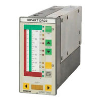
User Manuals: Siemens 6DR2210 Process Controller
Manuals and User Guides for Siemens 6DR2210 Process Controller. We have
1
Siemens 6DR2210 Process Controller manual available for free PDF download: Manual
Siemens 6DR2210 Manual (270 pages)
Brand:
Siemens
| Category:
Controller
| Size: 4.04 MB
Table of Contents
Sipart Dr22 6Dr2210
3
Edition
5
Table of Contents
7
Safety Notes and Scope of Delivery
9
Range of Application
10
Design (Hardware)
11
Function Principle
14
Standard Controller
14
Description of the Option Modules
15
CPU Self-Diagnostics
22
Data Storage, User Program Memory
23
Functional Description of the Structure Switches
24
Analog Input Signal Processing Permanently Connected
24
Analog Input Signal Processing Freely Connected (S4 = 1)
27
Arithmetic Ar1 to Ar6
29
Function Transmitter Fu1 and Fu2
29
Maximum Value Selection MA1 to MA3
29
Minimum Value Selection Mi1 to Mi3
30
Correction Computer for Ideal Gases Re1
30
Switch for Analog Variables AS1 to AS5
35
Comparator with Adjustable Hysteresis Co1, Co2
35
AND NOT Function (NAND) Na1, Na2
35
OR NOT Function (NOR) No1, No2
35
Digital Input Signal Processing
36
Digital Inputs BE1 to BE14
36
Assignment and Direction of Effect of the Digital Inputs
37
Linking the Digital Inputs BE1 bis BE14 to the Control Signals Via the SES
37
Functional Explanation of the Digital Control Signals
41
Controller Types (S1, S49 to S53)
42
General, Recurrent Functions
42
S1 = 0: Fixed Setpoint Controller with 2 Independent Setpoints
50
S1= 1: Fixed Setpoint Controller with 2 Dependent Setpoints
53
DDC Fixed Setpoint Controller
54
Follow-Up Controller, Synchronized Controller, SPC-Controller
60
S1 = 4: Commanded Ratio Controller
66
S1 = 5: Cascade Control
71
S1 = 6: Ratio-Cascade Control
76
S1 = 7/8: Override Control
79
Process Display
85
S1 = 10: Fixed Setpoint Controller with 1 Setpoint (Control System Coupling)
86
S1 = 11: Follow-Up Controller Without Int/Ext Switching (Control System Coupling)
87
Double Fixed Setpoint/Follow-Up Controller
88
Control Algorithm, Parameter Control, Adaptation
91
Control Algorithm
91
Controller Output Structures (S2, S61 to S68)
101
S2 = 0: Continuous (K) Controller
101
S2 = 1: Three-Position Step (S) -Controller with Internal Feedback
106
Three-Position Step (S) -- Controller with External Feedback
109
Analog Output Signal Processing (S69 to S75, S247 to S257)
122
Digital Output Signal Processing (S76 to S93 and S258 to S266)
123
Limit Value Alarms (S94 to S100, S267 to S268)
126
Restart Conditions (S99, S100)
128
Serial Interface and PROFIBUS-DP (S101 to S107)
128
Technical Data
129
General Data
129
Standard Controller
131
Technical Data of the Options Modules
135
2 Installation
145
Mechanical Installation
145
Electrical Connection
145
Connection Standard Controller
149
Wiring of Option Modules
152
Alternative Connection for I- and U-Input
160
Connection of the Interface
165
3 Operation
169
Process Operation
169
Selection Level
171
Configuring Level (Parameterization and Structuring Mode)
174
Paramterization
174
Parameterization Mode Onpa (Online Parameters)
175
Parameterization Mode Adap (Adaptation)
177
Structuring Mode Ofpa (Offline Parameters)
184
Structuring Mode Past (Parameter Control)
186
Structuring Mode Strs (Structure Switches)
188
Structuring Mode Fdef (Define Functions)
203
Structuring Mode Fcon (Connect Functions, Connection)
204
Structuring Mode Fpos (Position Functions)
207
Structuring Mode Fpst (Functions Preset, Factory Setting)
211
Structuring Mode Apst (All Preset, Factory Setting)
212
Set Structuring Mode CAE4/CAE5 -- UNI Module(S)
213
Measuring Range for MV (Sens=MV.)
214
Measuring Range for U, I (Sens=MV.)
214
Measuring Range for Thermocouple with Internal Reference Point (Sens=Tc.in)
215
Measuring Range for Thermocouple with External Reference Point (Sens=Tc.eh)
215
Measuring Range for PT100-4-Wire and PT100-3-Wire Connection (Sens=Pt.3L/Pt.4L)
215
Measuring Range for PT100-2-Wire Connection (Sens=Pt.2L)
216
Measuring Range for Resistance Potentiometer (Sens=R._ for R < 600 W, Sens=R. for R< 2.8 Kw)
216
4 Commissioning
217
Adapting the Controller Direction of Effect to the Controlled System
217
Setting the Split Range Outputs and the Actuating Time in K-Controllers (S2 = 0)
219
Adaptation of the S-Controller to the Actuating Drive
220
Setting the Filter and the Response Threshold
221
Automatic Setting of Control Parameters
222
Manual Setting of the Control Parameters
226
Manual Setting of the Control Parameters
227
5 Maintenance
229
General Information and Handling
229
Spare Parts List
233
6 Ordering Data
235
7 Application Examples for Configuring the Controller
237
8 Configuring Tool
243
9 Explanation of Abbreviations
255
Index
261
Advertisement
Advertisement
Related Products
Siemens 6DR63 Series
Siemens 6DR2410
Siemens 6DR2210-4
Siemens 6DR2210-5
Siemens 6DR2410-4
Siemens 6DR2410-5
Siemens 6ES7 321-7BH01-0AB0
Siemens 6ES7 322-5FF00-0AB0
Siemens 6ES7 331-7NF00-0AB0
Siemens 6ES7 332-7ND00-0AB0
Siemens Categories
Industrial Equipment
Controller
Control Unit
Oven
Washer
More Siemens Manuals
Login
Sign In
OR
Sign in with Facebook
Sign in with Google
Upload manual
Upload from disk
Upload from URL