Sign In
Upload
Manuals
Brands
Siemens Manuals
Controller
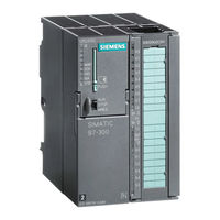
CPU 316-2 DP
Siemens CPU 316-2 DP Manuals
Manuals and User Guides for Siemens CPU 316-2 DP. We have
1
Siemens CPU 316-2 DP manual available for free PDF download: Reference Manual
Siemens CPU 316-2 DP Reference Manual (192 pages)
CPU Specifications
Brand:
Siemens
| Category:
Controller
| Size: 2.36 MB
Table of Contents
Table of Contents
13
Control and Display Elements of the Cpus
18
Control and Displays Elements
18
Figures
18
The Differences in Control and Display Elements between Cpus
18
Status and Fault Displays of the Cpus
19
Mode Selector Switch
20
Backup Battery/Accumulator
21
Using a Backup Battery or Accumulator
21
Memory Card
22
MPI and PROFIBUS-DP Interface
23
CPU Interfaces
23
Clock and Runtime Meter
26
Characteristics of the Clock of the Cpus
26
Communication Options of the CPU
27
CPU Communication Options
28
Connection Resources for Cpus 312IFM to 316-2 DP
30
Principle of Connection Resource Allocation for CPU
31
Communication Resources for CPU
31
Testing Functions and Diagnostics
35
The Principle of Forcing with S7-300 Cpus (CPU 312IFM to 316-2DP)
37
Diagnostics with STEP 7
38
Diagnostic Leds of the CPU
38
Cpus - Technical Specifications
40
Display of the States of the Interrupt Inputs of the CPU 312 IFM
42
Start Information for ob 40 for the Interrupt Inputs of the Integrated I/Os
42
Front View of the CPU 312 IFM
43
Wiring Diagram of the CPU 312 IFM
50
Basic Circuit Diagram of the CPU 312 IFM
52
Cpu 313
53
Cpu 314
56
Cpu 314Ifm
59
Start Information for ob 40 for the Interrupt Inputs of the Integrated I/Os
60
Display of the States of the Interrupt Inputs of the CPU 314 IFM
61
Front View of the CPU 314 IFM
62
Characteristic Features of the Integrated Inputs and Outputs
66
Wiring Diagram of the CPU 314 IFM
72
Basic Circuit Diagram of the CPU 314 IFM
73
Basic Circuit Diagram of the CPU 314 IFM (Digital Inputs/Outputs)
74
Connecting 2-Wire Measurement Transducers to the Analog Inputs
75
Wiring of 4-Wire Measurement Transducers to the Analog Inputs
75
Cpu 315
76
Cpu 315-2 Dp
79
Cpu 316-2 Dp
82
Cpu 318-2
87
2 CPU 31X-2 as DP Master/Dp Slave and Direct Communication
91
Information on DPV1 Functionality
91
DP Address Areas of the Cpus 31X-2
91
CPU 31X-2 as DP Master
91
Diagnostics of the CPU 31X-2 as DP Master
91
CPU 31X-2 as DP-Slave
91
Meaning of the BUSF LED of the CPU 31X-2 as DP Master
96
Reading Diagnostic Data with STEP 7
97
Diagnostics with CPU 315-2DP < 315-2AF03
98
Diagnostics with CPU 31X-2 (315-2DP as of 315-2AF03)
99
Diagnostic Addresses for DP Master and DP Slave
100
Event Detection of the CPU 31X-2 as DP Master
101
Evaluating RUN-STOP Transitions of the DP Slaves in the DP Master
102
Transfer Memory in a CPU 31X-2 Operating as DP Slave
104
Example of an Address Area Configuration for Transfer Memory
105
Diagnosis of the CPU 31X-2 Operating as DP-Slave
108
Meaning of the BUSF Leds in the CPU 31X-2 as DP Slave
109
Diagnosis with Leds
109
Fetching Diagnostic Data with STEP 5 and STEP 7 in the Master System
110
Reading out the Diagnostic Data
110
Diagnostic Addresses for DP Master and DP Slave
112
Event Detection of the CPU 31X-2 as DP Slave
113
Evaluating RUN-STOP Transitions in the DP Master/Dp Slave
113
Format of the Slave Diagnostic Data
114
Structure of Station Status 1 (Byte 0)
115
Structure of Station Status 2 (Byte 1)
116
Structure of Station Status 3 (Byte 2)
116
Structure of the Master PROFIBUS Address (Byte 3)
117
Structure of the Manufacturer Identification (Bytes 4 and 5)
117
Structure of the Module Diagnosis of the CPU 31X-2
118
Module Diagnostics
118
Structure of the Station Diagnosis
119
Station Diagnostics
119
Byte X +4 to X +7 for Diagnostic and Hardware Interrupt
120
Interrupts
121
Direct Communication Using CPU 31X-2
122
Direct Data Exchange
122
Diagnostic Address for Receiver with Direct Communication
123
Event Detection by CPU 31X-2 Acting as Receiver in
123
Diagnosis with Direct Communication
123
Evaluation of the Station Failure of the Sender During
124
Component Parts of the Cycle Time
126
Response Time
127
Shortest Response Time
128
Longest Response Time
129
Operating System Processing Times of the Cpus
130
Process Image Update of the Cpus
131
CPU-Specific Factors for the User Program Processing Time
131
Updating the S7 Timers
131
Update Time and SFB Runtimes
132
Overview of the Bus Runtime on PROFIBUS-DP at 1.5 Mbps
133
Extending the Cycle by Nesting Interrupts
134
Calculation Examples for Cycle Time and Response Time
134
Response Time of the Cpus to Process Interrupts
138
Interrupt Response Time
138
Diagnostic Interrupt Response Times of the Cpus
139
Calculation Example for the Interrupt Response Time
140
Reproducibility of the Delay and Watchdog Interrupts of the Cpus
141
Differences between CPU 3182 and Cpus 312 IFM to 3162 DP
144
Sample Configuration
146
Memory Cards
148
The Differences between the Cpus 312 IFM to 318 and Their Previous Versions
148
Dimensioned Drawing of the CPU
163
Dimensioned Drawing of the CPU 313/314/315/315-2 DP/316-2DP
164
B-3 Dimensioned Drawing of the CPU 318-2
165
Dimensioned Drawing of the CPU 314 IFM, Front View
166
Dimensioned Drawing of the CPU 314 IFM, Side View
167
Advertisement
Advertisement
Related Products
Siemens CPU 314 IFM
Siemens CPU 315
Siemens CPU 318-2
Siemens CPU 312 IFM
Siemens CPU 318-2 DP
Siemens CPU 313
Siemens CPU 317T-2 DP
Siemens CPU 410-5H Process Automation
Siemens CPU 410 SMART
Siemens CPU 1515SP PC2 IndOS
Siemens Categories
Industrial Equipment
Controller
Control Unit
Oven
Washer
More Siemens Manuals
Login
Sign In
OR
Sign in with Facebook
Sign in with Google
Upload manual
Upload from disk
Upload from URL