Sign In
Upload
Manuals
Brands
Siemens Manuals
Controller
ERTEC 200P
Siemens ERTEC 200P Manuals
Manuals and User Guides for Siemens ERTEC 200P. We have
1
Siemens ERTEC 200P manual available for free PDF download: Manual
Siemens ERTEC 200P Manual (501 pages)
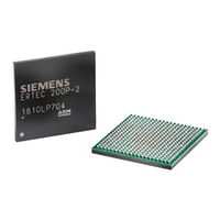
Enhanced Real-Time Ethernet Controller
Brand:
Siemens
| Category:
Controller
| Size: 4.41 MB
Table of Contents
Table of Contents
6
1 Introduction
15
Overview of the ERTEC 200P
15
Mechanisms for PROFINET IO (NRT Communication)
15
Mechanisms for PROFINET IO (RT Communication) RTC1/2
15
Mechanisms for PROFINET IO (IRT Communication) RTC3
15
Mechanisms for PROFINET IO (IRT High Performance Communication) RTC3
16
ERTEC 200P Data
17
System Reliability
18
Electromagnetic Compatibility (EMC)
18
ERTEC 200P Use Cases
19
Use Case 1 (UC1): Operation with External Host
19
Figure 1: ERTEC 200P Use Cases
19
Use Case 2 (UC2): Operation Without External Host
20
Figure 2: Application Operation with External Host
20
Application Notes
21
EMC SDRAM Interface
21
Figure 3: Application Operation Without External Host
21
EMC Burst Flash Interface
22
No Free-Running Frequency at Quartz Break
22
16-Bit Data Access over XHIF in Buffered Mode
23
2 Description of Functions
24
Block Diagram
24
General Function Description (Motivation)
24
Figure 4: ERTEC 200P Step2 Block Diagram
24
Description of Individual ERTEC 200P Blocks
25
Processor Subsystem (ARM926)
25
Block Diagram
26
Features
26
Figure 5: ARM926 Subsystem
26
ARM926EJ-S Processor
27
Cache Structure of ARM926EJ-S
27
ARM926 Tightly Coupled Memories (ARM926_TCM)
28
Memory Management Unit (MMU)
29
Table 1: Types of ARM926EJ-S Access to I/D-TCM / AHB
29
ARM926 Embedded Trace Macrocell (ETM9), Trace Buffer (ETB11)
30
Bus Interface of the ARM926 Processor
30
ARM926EJ-S Debug Interface
31
Debug Configuration
31
Debug Support
31
Figure 6: JTAG Chain
31
Boot Process for the ERTEC 200P
32
Table 2: Boot, ERTEC 200P Boot Modes
32
Primary Boot Loader
34
Table 3: Boot Mode Adjustment
36
Boot Mode 1
37
Table 4: Startup Times
37
Boot Modes 5 and 6 (Booting with SPI Master)
38
Boot Mode 7 (Booting with External Host)
40
Memory Swapping by the Secondary Boot Loader
43
Secondary Boot Loader
43
AMBA (Internal Bus System)
43
Characteristics of the Bus System in ERTEC 200P
43
AHB Subsystem (Multi-Layer AHB)
44
Endianness
44
Table 5: Internal Bus System, Parameters of Internal Buses
44
AHB Arbiters
45
AHB Multi-Layer Configuration
45
Table 6: Fixed Priority Assignment (no Default)
45
AHB Burst Breaker
46
Table 7: AHB Master-Slave Coupling
46
APB Subsystem (Peripheral Bus)
47
Figure 7: AHB/APB Bridge, Block Diagram
49
Figure 8: APB Bridge, Timing
50
Address Range and Acknowledgement Delay Monitoring
51
APB Decoder
51
Monitoring at the AHB Side
51
Monitoring at the APB Side
52
Monitoring at the EMC
52
Monitoring in the Individual Modules
52
Table 8: Access Error Register (from SCRB)
53
Interface
54
Overview
54
Interrupt Acquisition
55
Interrupt Masking / Priorisation
57
Interrupt Post-Processing
58
Debug Functions
59
Miscellaneous
59
Special Functions
59
Synchronizing the Inputs
59
Bus Interface
60
Sequences
60
Operating Rules
61
Startup/Shutdown
62
Interrupt Sources for ARM-IRQ
63
Confirmation Delay in the Memory Controller (EMC) Address Area
68
Interrupts for Accesses to Missing Addresses
68
Table 9: Host INTA, Interrupt Sources
68
High-Priority Interrupts for Debugging
69
Interrupt Sources for ARM-FIQ
69
Table 10: Host INTB, Interrupt Sources
69
Address Mapping
70
Register Description
76
Host ICU (Perif: Event Unit)
103
GDMA (Direct Memory Access)
103
GDMA Function Description
103
AHB Interfaces
104
Details
104
Job Priorities
104
Usage
114
Result
115
Memory
116
ERTEC 200P GDMA Use Cases
117
Interrupts
117
Using the Job Start and HW_REQ Signal List
117
DMA with UART Interface
125
GDMA-IP Bugs
125
Address Mapping
126
Register Description
129
Table 13: the DMA RAM Address Space
154
EMC (External Memory Controller)
157
Block Diagram of the EMC
158
Figure 9: EMC Block Diagram
158
EMC Reset and Clock
159
Figure 10: EMC Interface with Two SDRAM / Two Burst Flash Configuration
159
Figure 11: EMC Interface with Only One SDRAM / One Burst Flash Configuration
160
Figure 12: EMC Interface with Asynchronous RAM
160
AHB-Slave Interface
161
Figure 13: EMC, Address Space
161
EMC Notes
162
Maximum Number of Wait Cycles
162
Remapping
162
Shift Mode with the Asynchronous EMC Interface
162
Control of an External Driver
163
QVZ Acknowledgement Delay
163
Figure 14: EMC, Notation Definition for a Read Access (ASYNC)
164
Read Access
164
Timing of the Asynchronous Memory Interfaces
164
Figure 15: EMC, Notation Definition for a Write Access (ASYNC)
165
Write Access
165
Application Examples
166
Figure 16: EMC, Application Example SDRAM
166
Figure 17: EMC, Application Example: Combination of SDRAM and Asynchronous Interfaces
166
Figure 18: EMC, Interface Signals
167
Interface Signals
167
Table 14: EMC, Connection to the Memory Devices
168
Address Mapping
169
Table 15: EMC - Address Map
169
Register Description
170
Host Interface - Parallel (XHIF)
182
Block Diagram of the Host Interface
182
Figure 19: Block Diagram of the Host Interface
182
Function Description (XHIF)
183
Figure 20: XHIF, Symbol and Signals
184
AHB Master Interface
186
APB Slave Interface
186
Figure 21: XHIF Interface Adjustment
186
XHIF Configuration
186
Application Information
187
Address Mapping
189
Register Description
190
Peripheral Interface
197
Figure 22: Block Diagram of the Peripheral Interface
198
Address Mapping
199
APB Interface
199
Register Description
203
Profinet-Ip
230
AHB Interface
230
Interrupt Management
230
PN-IP Interfaces
230
Figure 23: Block Diagram of PN-ICU for Pn_Irqx(0/1:0) Group Interrupts
231
Figure 24: Block Diagram of PN-MUX for Pn_Irqx(2:1/15:2) Single Interrupts
232
PN-PLL (Incl. 3X Application Timer Blocks)
232
Figure 25: PNPLL with 3 Application Time Blocks (Application Connection)
233
EDC in PN-IP Rams
234
Recommended Parameter Assignment for ERTEC 200P
234
Ethernet PHY (Integrated)
235
Status of the Integrated PHY
236
CRU (Clock and Reset Unit)
236
Clock Generation and Distribution
236
Clock System
236
Table 16: Overview of ERTEC 200P Clocks
236
Figure 26: Quartz Wiring
237
PLL Clock Generation
237
Clock Monitoring
238
Clock Source for JTAG
238
Clock Source for the Phys and Ethernet Macs
238
Figure 27: Clock Source for the Ethernet Connection
238
Lock Timer 1
238
Lock Timer 2
238
Lock Monitor
239
Reset System
241
Figure 28: ERTEC 200P Reset Matrix
242
Asynchronous Poweron Reset
243
Figure 29: PLL Startup Phase
243
Asynchronous Hardware Reset
244
Asynchronous JTAG Reset
244
Asynchronous ARM926 Watchdog Reset
245
Asynchronous Software Reset for ERTEC 200P (Without PN-IP)
245
Asynchronous Software Reset for PN-IP
245
Asynchronous Software Reset for the ARM926EJ-S Core
246
Synchronous Software Reset (PN-IP, PER-IF, Host Interface)
246
APB Peripherals
247
Table 17: Data Width of Peripherals
247
Figure 30: Block Diagram of the IO Filter
248
Figure 31: Block Diagram of the Filter Structure of a Channel
248
I-Filter
248
Figure 32: Block Diagram of the Central Clock Divider
249
Operating Principle of the RC Filter
250
Table 18: Sample Filter Times for I-Filter
250
Address Mapping
251
Figure 33: Signal in Signal Filtering
251
Register Description
253
ARM926 Watchdog
260
Block Diagram
260
Figure 34: Block Diagram ARM926 Watchdog
260
Overview
260
Figure 35: XWD_OUT0/ WD_INT Signal Sequence
263
Signal Waveforms
263
Figure 36: XWD_OUT1 Signal Sequence
264
Starting the Watchdog
264
Write Protection of the Watchdog Register
264
Address Mapping
265
Notes
265
Register Description
266
Overview
269
Timer 0 - 5
269
TIMER_TOP Functionality
270
Figure 37:TIMER Block Diagram
273
Timer Module
273
Overview of the Count Modes
280
Timing Requirements
281
Operating Rules
282
Connections on ERTEC 200P Toplevel
283
Address Mapping
285
Register Description
286
F-Counter
302
Address Mapping
303
Application Information
303
Figure 38: F-Timer Block Diagram
303
Function Description
303
Register Description
304
Uart1
305
UART Baud Rates
306
Figure 39: Baud Rates UART When F
307
Address Mapping
308
Register Description
310
Baudrate Generator
325
IO Expansion Unit
325
I²C
325
Important Software Rules
326
Address Mapping
328
Register Description
329
SPI1/2 (Serial Peripheral Interface)
335
Features of the SPI Interface
337
SSPMS IP Extension
338
SSPMS IP Integration
339
Figure 40: SPI Block Diagram
340
Send Support with Pause between Individual Characters
342
Figure 41: SPI Flash: Serial Output Timing
343
Figure 42: SPI Flash: Serial Input Timing
343
SPI Flash Boot
343
Table 19: Timing Parameters for SPI Flash (75 Mhz)
344
Address Mapping
345
Register Description
345
GPIO (General Purpose Input / Output)
348
GPIO Module Function Description
349
Figure 43: Block Diagram of a GPIO Module
350
Figure 44: GPIO, IO Circuit
352
Integration of the GPIO Module
352
GPIO Assignment
353
GPIO Pad Multiplexing
353
Table 20: Overview of Alternate Functions (a - C)
355
Address Mapping
356
Register Description
357
Hardware Identifier Register
365
SCRB (System Control Register Block)
365
Table 21: ERTEC 200P, ID Register
365
Boot Register
366
Config Register
366
Table 22: Bootmodi Adjustment
366
Reset Registers
367
Table 23: Configuration Adjustment
367
ACCESS_ERROR and QVZ Register
368
Memory Swapping
368
PLL Status Register
368
AHB Burst Breaker Register
369
ARM Control Register
369
GPIO Control Register
369
PHY Register
369
ARM926 Mapping
370
EDC Register
370
I²C Clock Divider
370
PAD Control Register
370
Clear DMA Request
373
Ext. Driver Enable
373
SD Signal Handling
373
SPI Mode
373
SPI Parity Error
373
XHIF Mode
373
Address Mapping
374
Register Description
376
Memory Mapping
415
Memory Mapping ARM926-I
415
ARM926-D Memory Mapping
416
PN-IP Memory Mapping
417
Host if Memory Mapping
418
GDMA Memory Mapping
421
Detailed Address Mapping
422
Register Description
425
3 Io Interface
426
Overview
426
Table 24: IO - Pin Count Overview
426
Detailed Signal Description
427
Table 25: Signal Description and Pinning ERTEC 200P
449
Strapping Pins
450
IO Timing
451
Figure 45: Definition of Time Reference
451
EMC Timing
452
SRAM Timing
452
SRAM Timing for Read Access
452
SRAM Timing for Write Access
453
Burstmode Flash Timing
454
SDRAM Timing
455
SDRAM Timing for Read Access
457
SDRAM Timing for Write Access
458
Host-Interface Timing
459
Separate RD/WR
459
XHIF Timing
459
Common RD/WR
461
SPI Timing
463
PN-IP Timing
464
Figure 46: MII Interface
464
Figure 47: MDIO Interface
464
MDIO Timing
464
MII Timing
464
MII Timing at Integrated PHY
464
Integrated PHY Timing
465
MDIO Timing at the Integrated PHY
465
PHY FX Timing
465
PHY LED Timing
465
PNPLL Timing
465
Table 26: Constraining PNPLL Interface
467
Timing for Time Synchronization
467
SPI Timing
468
Spi1
468
Spi2
468
UART Timing
470
Uart1
470
Uart2
470
Uart3
470
Uart4
470
GPIO Timing
471
I²C Timing
471
I²C - Apb
471
I²C - Pn-Ip
471
JTAG Timing
471
ARM926 Trace Timing
472
Figure 48: Debug Interface
472
Figure 49: ARM926 Trace Interface
472
4 Layout and Design Hints
474
EMC Measures
474
ESD Protection
474
Immunity to ESD
474
Package Power Distribution
474
Spike Filter
474
Figure 50: Spike Filter Implementation
475
Oscillator Circuit
476
Circuit with Ext. Crystal
476
Figure 51: Oscillator Circuitry Layout Example
477
Circuit with External Crystal Oscilllator
478
Figure 52: Connection of an External Oscillator
478
PLL Wiring (Power Supply)
479
Figure 53: Recommended for PLL Power Supply Filter
479
Test Signal Configuration
480
JTAG Wiring
480
PHY Wiring
481
PHY-TX Wiring
481
Figure 54: UTP Circuit
482
PHY-TX Wiring - Not Used
482
PHY-FX Wiring
483
Figure 55: FX Circuit
484
Figure 56: FX Circuit Unused Pins
485
GPIO Circuit
485
PHY-FX Wiring - Not Used
485
PHY-SD Wiring - Avago QFBR-5978AZ
485
Pxsd Circuit
485
Wiring of Pins Not Used
486
Figure 57: SD Level Translation Circuit
486
Figure 58: Recommendation for Handling Special Function Signals
487
Operating Conditions
488
Power up
488
Wiring of CTRL-STBY
488
Power-Up Sequence (PLL)
489
PLL Behavior
489
Following Crystal Break
489
Upon Temporary Clock Failure
489
Readiness of Internal Resources Once a Reset Is Cleared
490
Pull-Up/Pull-Down Resistor Values
490
Schmitt Trigger Characteristics
490
Module and ASIC Code (Chip ID)
490
Power Dissipation
491
5 Package
493
Package Drawing
493
Ball Layout
493
Figure 59: 400-Ball SIP-FPBGA
493
Marking (Printed)
495
Order Codes
495
Sip - FPBGA400 Thermal Characteristics
495
Max. Junction Temperature T
496
Solder Profile
497
Packing Information
498
Tray
498
Tape&Reel
498
6 Quality
499
Hard-Error FIT Rates
499
Soft-Error FIT Rates
499
7 Miscellaneous
500
Abbreviations
500
Literature List
501
Advertisement
Advertisement
Related Products
Siemens HydroRanger 200 HMI
Siemens ERTEC 200P-2
Siemens BACNET 2584
Siemens BACNET 2590
Siemens Albatros 2 RVS13 Series
Siemens Albatros 2 QAA75 Series
Siemens Albatros 2 QAA78 Series
Siemens Albatros 2 QAA55 Series
Siemens LOGO! 24RC
Siemens LOGO! 24RCL
Siemens Categories
Industrial Equipment
Controller
Control Unit
Oven
Washer
More Siemens Manuals
Login
Sign In
OR
Sign in with Facebook
Sign in with Google
Upload manual
Upload from disk
Upload from URL