Sign In
Upload
Manuals
Brands
Siemens Manuals
Network Hardware
RWF40 Series
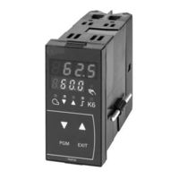
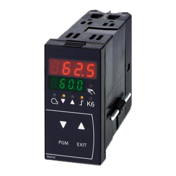
Siemens RWF40 Series Universal Controller Manuals
Manuals and User Guides for Siemens RWF40 Series Universal Controller. We have
4
Siemens RWF40 Series Universal Controller manuals available for free PDF download: User Manual, Installation, Use And Maintenance Instructions, Quick Start Manual
Siemens RWF40 Series Installation, Use And Maintenance Instructions (52 pages)
Power controller
Brand:
Siemens
| Category:
Controller
| Size: 0.93 MB
Table of Contents
Italian
2
Table of Contents
2
Schema DI Principio
3
Dati Tecnici
4
Impiego
12
Descrizione
12
Dimensioni
12
Installazione
14
Applicazione Sul Bruciatore
14
Applicazione a Quadro
16
Accesso al Regolatore Rwf40
16
Modalità DI Impostazione
18
Livello: Livello Utente
22
Modifica Dei Setpoints
22
Funzionamento Manuale DI un Bruciatore Modulante
22
Funzionamento Manuale DI un Bruciatore Bistadio
22
Relè K1 - K2 - K3 - K6
24
Livello: Livello Parametri
24
Immissione Dei Parametri
24
Modi Operativi
26
Funzionamento al Minimo
26
Funzionamento in Potenza
26
Bruciatore Modulante, Uscita a 3 Punti
26
Bruciatore Modulante, Uscita Modulante
26
Bruciatore Bistadio, Uscita a 3 Punti
28
Bruciatore Bistadio, Uscita Modulante
28
Spegnimento DI Sicurezza
28
Setpoint Predelimitato
28
Avviamento a Freddo Dell'impianto
28
Descrizione Parametri
30
Livello: Livello Configurazione
36
Modifica del Codice DI Configurazione
36
Configurazione C111
38
Configurazione C112 - C113
39
Affinamento Della Regolazione
40
Cosa Fare Se
48
English
3
General Wiring Diagram
3
Technical Data
8
Use
13
Installation
15
Fitting on the Burner
15
Mounting on the Control Panel
17
Access to the Rwf40 Controller
17
Setting Mode of the Rwf40 Controller
20
Level: USER LEVEL
23
Changing the Setpoints
23
Manual Operation of a Modulating Burner
23
Manual Operation of a Two-Stage Burner
23
Relays K1 - K2 - K3 - K6
25
Level: Parameter Level
25
Parameter Input
25
Operating Modes
27
Low-Fire Operation
27
High-Fire Operation
27
Modulating Burner, 3-Position Output
27
Modulating Burner, Modulating Output
27
Two-Stage Burner, 3-Position Output
29
Two-Stage Burner, Modulating Output
29
Safety Shutdown
29
Predefined Setpoint
29
Cold Start of the Plant
29
Description of the Parameters
31
Level: Configuration Level
37
Changing the Configuration Code
37
Configuration C111
38
Configuration C112 - C113
39
Adjustment Refinement
41
What to Do if
50
German
3
Stromlaufschaltplan
3
Technische Angaben
6
Einsatz
13
Beschreibung
13
Abmessungen
13
Installation am Brenner
15
Installation auf Schalttafel
17
Zugriff zum Regler Rwf40
17
Einstellung des Reglers
19
Ebene: Bedienerebene
23
Sollwerte Ändern
23
Handbetrieb, Brenner Modulierend
23
Handbetrieb, Brenner 2-Stufig
23
Relais K1 - K2 - K3 - K6
25
Ebene: Parameterebene
25
Parameter Eingeben
25
Betriebsarten
27
Kleinlastbetrieb
27
Grosslastbetrieb
27
Brenner Modulierend, 3-Punktausgang
27
Brenner Modulierend, Stetiger Ausgang
27
Brenner 2-Stufig, 3-Punktausgang
29
Brenner 2-Stufig, Stetiger Ausgang
29
Sicherheitsabschaltung
29
Sollwertvorgabe
29
Kaltstart der Anlage
29
Beschreibung der Parameter
31
Ebene: KONFIGURATIONSEBENE
37
Konfigurationscodes Ändern
37
Konfiguration C111
38
Konfiguration C112 - C113
39
Feinregelung
41
Was Ist, wenn
49
French
3
Schema de Principe
3
Données Techniques
10
Description
13
Dimensions
13
Emploi
13
Application Sur Le Brûleur
15
Application Au Tableau
17
Acces Au Regulateur Rwf40
17
Modalite Pour la Saise du Regulateur Rwf40
19
E Niveau: Niveau Opérateur
23
Modifier Les Valeurs de Consigne
23
E Niveau: Niveau Paramétrage
25
Saisie des Paramètres
25
Description des Parametres
31
E Niveau: Niveau Configuration
37
Modification des Codes de Configuration
37
Perfectionnement du Reglage
41
FUNZIONE "Tune
42
FUNKTION "Tune
43
Tune" FUNCTION
44
FONCTION "Tune
45
Que Se Passe-T-Il si
51
Advertisement
Siemens RWF40 Series User Manual (56 pages)
Compact Universal Controller
Brand:
Siemens
| Category:
Controller
| Size: 0.81 MB
Table of Contents
Table of Contents
3
1 Introduction
6
General Notes
6
Description
6
Typographical Conventions
7
Warning Symbols
7
Notification Symbols
7
Presentation
7
2 Type of Unit
8
Type Field
8
3 Installation
9
Installation Site and Climatic Conditions
9
Dimensions
9
Side-By-Side Mounting
10
Mounting in a Panel Cutout
10
Cleaning the Front Panel
11
Removing the Controller Module
11
4 Electrical Connections
12
Installation Notes
12
Block Diagram
13
Assignment of Terminals
14
Galvanic Separation
17
5 Operating Modes
18
Low-Fire Operation
18
High-Fire Operation
18
Modulating Burner, 3-Position Output
18
Modulating Burner, Modulating Output
19
Two-Stage Burner, 3-Position Output
19
Two-Stage Burner, Modulating Output
20
Safety Shutdown
20
Pre-Defined Setpoint
20
Setpoint Changeover "SP1 / SP2", Analog Setpoint Shift
21
Setpoint Changeover "SP1" / External Setpoint
22
Setpoint "SP1", Analog / Binary Setpoint Shift
23
External Setpoint, Binary Setpoint Shift
24
Weather-Dependent Setpoint Shift
25
Heating Curve Slope
26
Response Threshold "Q
27
Cold Start of the Plant
28
6 Operation
29
Basic Display
30
Meaning of the Display and Buttons
30
User Level
31
Changing the Setpoints
31
Manual Operation of a Modulating Burner
33
Manual Operation of a Two-Stage Burner
33
Start Self-Setting
34
Display of the Software Version and Unit of Actual Value
34
Parameter Level
35
Enter Parameters
35
Configuration Level
35
Changing the Configuration Code
35
7 Parameter Settings
36
8 Configuration
38
C111 Inputs
38
C112 Limit Comparator, Controller Type, Setpoint "SP1", Locking
40
C113 Unit Address, Dimensional Unit, Out-Of-Range
44
SCL Scaling of Standard Signal Range Start, Analog Input 1
45
SCH Scaling of Standard Signal Range End, Analog Input 1
45
SCL2 Scaling of Standard Signal Range Start, Analog Input 2
45
SCH2 Scaling of Standard Signal Range End, Analog Input 2
46
SPL Lower Setpoint Limit
46
SPH Upper Setpoint Limit
46
OFF1 Actual Value Correction for Analog Input 1
46
OFF2 Actual Value Correction for Analog Input 2
46
OFF3 Actual Value Correction for Analog Input 3
46
Df1 2 Nd Order Digital Filter for Analog Input 1
46
9 Self-Setting Function
47
Self-Setting Function in High-Fire Operation
47
Checking the Controller Parameters
49
10 What to Do if
50
Numbers Are Flashing on the Display
50
11 Technical Data
51
Inputs
51
Analog Input 1 (Actual Value)
51
Analog Input 2 (External Setpoint, Setpoint Shift)
51
Analog Input 3 (Outside Temperature)
52
Binary Input "D1
52
Binary Input "D2
52
Outputs
52
Output 1 (Release of Burner)
52
Output 2, 3 (3-Position Output)
52
Output 4 (Limit Comparator)
52
Output 5, Modulating Output (Option)
53
Transducer Supply
53
Interface RS-485 (Optional)
53
General Ratings
53
Measured Value Accuracy
54
Measured Value Circuit Monitoring
54
Environmental Conditions
54
12 Current Settings
55
Process Data
55
Parameter Level
55
Configuration Level
56
Siemens RWF40 Series User Manual (15 pages)
Interface RS-485
Brand:
Siemens
| Category:
Network Hardware
| Size: 0.14 MB
Table of Contents
Master-Slave Principle
1
Application Examples
1
Transmission Mode (RTU)
2
Device Address
2
Data Format
2
Query
2
Communication Sequence
3
Process
3
Example
3
Data Query Sequence
4
Time Sequence
4
Communication During the Slave’s Internal Handling Time
4
Communication During the Slave’s Response Time
4
Structure of the Data Blocks
5
Data Structure
5
Fault Handling
5
Reply in the Event of Fault
5
Checksum (CRC16)
6
Calculation
6
Reading N Words
7
Data Query
7
Writing 1 Word
7
Reply
8
Data Type “Char“
8
Data Type “Float“
8
Address Tables
9
Process Data
9
Parameter Level
9
Configuration Level
9
Device Data
10
Remote Operation
10
Device State
11
Description of Operating Modes
12
RAM Parameter for Remote Operation
12
Operating Mode "LOCAL"
13
Operating Mode «REMOTE SETPOINT»
13
Operating Mode «FULLY REMOTE»
13
Mudulating Burner
14
Modulating Controller
14
Floating Step Controller
14
Advertisement
Siemens RWF40 Series Quick Start Manual (8 pages)
Compact Universal Controllers
Brand:
Siemens
| Category:
Controller
| Size: 0.31 MB
Advertisement
Related Products
Siemens RS-485
Siemens Rider 11 Bio
Siemens Rider 11, Rider 13 H,Rider 11 Bio
Siemens Rider 14 Pro
Siemens Rider 16 H
Siemens Rider 13 H Bio
Siemens RUGGEDCOM RX1511
Siemens RUGGEDCOM RX1400
Siemens SIMATIC NET RUGGEDCOM RX1536
Siemens Caracas Desk Rel. 2.0
Siemens Categories
Industrial Equipment
Controller
Control Unit
Oven
Washer
More Siemens Manuals
Login
Sign In
OR
Sign in with Facebook
Sign in with Google
Upload manual
Upload from disk
Upload from URL