Sign In
Upload
Manuals
Brands
Siemens Manuals
Network Card
S5-135U/155U
Siemens S5-135U/155U Manuals
Manuals and User Guides for Siemens S5-135U/155U. We have
1
Siemens S5-135U/155U manual available for free PDF download: System Manual
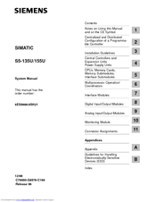
Siemens S5-135U/155U System Manual (560 pages)
Siemens Network Card System Manual
Brand:
Siemens
| Category:
Network Card
| Size: 4.46 MB
Table of Contents
Table of Contents
3
1 Notes on Using this Manual and on the CE Symbol
11
Notes on Using this Manual
11
Connector Assignments
13
A Appendix
13
Index
13
Notes on the CE Symbol
14
Notes for Machine Manufacturers
16
Safety Notes
17
2 Centralized and Distributed Configuration of a Programmable Controller
19
Application
20
Centralized and Distributed Configuration
21
Installing a PLC with Centralized Configuration
22
Installing a PLC with Distributed Configuration
23
Examples
24
3 Installation Guidelines
27
Principles of Installation of Systems for EMC
28
Overview of Possible Types of Interference
28
The most Important Basic Rules for Ensuring EMC
32
Installation of Programmable Controllers for EMC
34
Basic Rules for Assembling and Grounding the Inactive Metal
34
Parts
34
Example of Cabinet Assembly for EMC
35
Example of Rack and Wall Mounting for EMC
37
Wiring of Programmable Controllers for EMC
38
Routing of Cables
38
Equipotential Bonding
40
Shielding of Cables and Lines
41
Special Measures for Interference-Free Operation
43
Checklist for the Electromagnetically Compatible Installation of Control Systems
45
Power Supplies for Programmable Controllers and I/Os
46
Power Supplies for Control Systems with SIMATIC S5
46
Connecting the Programmable Controller and Load Power
47
Connecting Non-Floating or Floating Modules
52
Interference-Free Installation of Centralized and Distributed Interface Circuits
54
Interference-Free Installation of Distributed Interface Circuits
54
Interference-Free Connection of Monitors
56
Interference-Free Connection of a Monitor to the CP of the S5
56
Controller
56
Shielding and Grounding
57
Selection and Installation of Cabinets with SIMATIC S5
59
Types of Cabinet
60
Clearances in Cabinets
60
Removal of Power Dissipation from Cabinets
63
Examples for Determining the Type of Cabinet
64
Determining the Power Dissipation of Modules
65
4 Central Controllers and Expansion Units Power Supply Units
67
S5-135U/155U Central Controller
68
Technical Description
68
Installation
72
Release
75
Startup
76
Repair Guidelines
78
Technical Specifications
79
Expansion Units
81
Technical Description of the Expansion Units
82
Installing the Expansion Units
84
Technical Specifications of the Expansion Units
84
Power Supply Units
85
Product Overview
85
Leds and Controls
88
Setting and Connecting the Power Supply Unit
89
Expansion Units Power Supply Units
92
Installation Guidelines
92
Fault Indications/Fault Diagnostics
102
Maintenance and Repairs
106
Description of Internal Sequences in the Power Supply Unit
115
Technical Specifications of the Power Supply Units
117
6ES5 955-3NA12 Power Supply Unit
123
Technical Description
123
Setting the Power Supply Unit
126
Installation
129
Operation
130
Maintenance
132
Technical Specifications
134
Fan Submodules
136
Technical Description
136
Setting and Connecting the Fan Submodule
138
Technical Specifications
140
5 Cpus, Memory Cards, Memory Submodules, Interface Submodules
142
CPU 948B -3UA13 or CPU 948B -3UA23
142
Technical Description
142
Multiprocessor Operation
142
Installation and Startup
143
Interface Modules
150
Cpu
153
Interfaces of the CPU 948
153
Technical Specifications
155
Technical Description
157
Installation and Startup
158
Interfaces of the CPU 948
167
Technical Specifications
168
Cpu 928B -3Ub21
170
Technical Description
170
Installation and Startup
173
Technical Specifications
180
Cpu 928B
182
Technical Description
182
Installation and Startup
185
Technical Specifications
192
Cpu 928 -3Ua21
194
Technical Description
194
Installation and Startup
196
Technical Specifications
201
Technical Description
202
Installation and Startup
204
Technical Specifications
210
Technical Description
211
Installation and Startup
213
Technical Specifications
219
Flash EPROM Cards
220
Technical Description
220
Notes on Operation
220
Technical Specifications
221
Memory Submodules
222
Technical Description
222
Notes on Operation
222
Technical Specifications
223
Notes on Operation
224
Memory Submodules
224
Technical Description
224
RAM Submodules with Battery Backup
225
Technical Specifications
230
Interface Submodules
232
Installing and Removing the Interface Submodules
233
PG Submodule
235
V.24 Submodule
239
TTY Submodule
246
RS422 A/485 Submodule
252
SINEC L1 Submodule
258
Technical Specifications of the Interface Submodules
262
6 Multiprocessor Operation/Coordinators
263
Introduction
264
Starting the Multiprocessor Operation
265
Coordinator Modes
275
A Coordinator Module
277
Technical Description
277
Settings on the Coordinator
279
C Coordinator Module
280
Technical Description
280
Settings on the Coordinator
285
Technical Specifications of the Coordinators
290
7 Interface Modules
291
The 300 and 312 Interface Modules
292
Indicators and Controls
294
Modes/Jumper Assignments of the IM 300
295
The 301 and 310 Interface Modules
299
Indicators and Controls
300
Modes/Jumper Assignments of the IM 301
301
The 304 and 314 Interface Modules
303
Indicators and Controls
304
Modes/Jumper Assignments of the IM 304
305
Modes/Jumper Assignments of the IM 314
307
Technical Specifications
310
8 Digital Input/Output Modules
313
Technical Description
313
Design
316
Function of the Enable Inputs
317
Special Features of the 432 Digital Input Module
320
Setting the Module Address
326
Installation and Startup
326
Removing and Inserting Modules
330
Marking of Modules
332
Connecting the Signal Lines
333
Connection of Outputs in Parallel and Switching on the Load Via a Contact
334
Short-Circuit Protection and Fusing
336
Arc-Quenching for Inductive Loads
337
Common Technical Specifications
338
Specification Sheets for the Modules
342
9 Analog Input/Output Modules
383
Technical Description
384
Common Technical Specifications
385
The 460 Analog Input Module
386
Design
386
Function of the Enable Input
386
Special Features of the 460 Analog Input Module
390
Setting the Module Address
392
Removing and Inserting Modules
395
Marking of Modules and Front Connectors
397
Connecting the Signal Lines
398
Connection of Sensors
399
Connecting a Compensating Box for Thermal E.M.F. Measurement
401
Connecting Resistance Thermometers in the Standard Pt 100 Range
402
Connecting Resistance Thermometers in the Extended Pt 100 Range
403
Broken Wire Signal
404
Connecting Transducers
405
Measured-Value Representation
406
Technical Specifications
411
The 463 Analog Input Module
417
Design
417
Function of the Enable Input
417
Special Features of the 463 Analog Input Module
421
Setting the Module Address
421
Removing and Inserting Modules
424
Marking of Modules and Front Connectors
426
Connecting the Signal Lines
427
Measured-Value Representation
428
Technical Specifications
429
The 465 Analog Input Module
432
Design
432
Function of the Enable Input
432
Special Features of the 465 Analog Input Module
436
Setting the Module Address
438
Removing and Inserting Modules
441
Marking of Modules and Front Connectors
443
Connecting the Signal Lines
444
Connecting a Compensating Box for Thermal E.M.F. Measurement
445
Connecting Resistance Thermometers to the 465 Analog Input Module
446
Broken Wire Signal for Resistance Thermometers
448
Connecting Transducers
449
Measured-Value Representation
450
Technical Specifications
454
The 466 Analog Input Module
459
Design
459
Special Features of the 466 Analog Input Module
459
Startup
459
Removing and Inserting Modules
466
Marking of Modules and Front Connectors
468
Connecting the Signal Lines
469
Connecting Sensors to the 466 Analog Input Module
470
Measured-Value Representation
473
Technical Specifications
477
The 470 Analog Output Module
480
Design
480
Function of the Enable Input
480
Special Features of the 470 Analog Output Module
484
Setting the Module Address
484
Removing and Inserting Modules
487
Marking of Modules and Front Connectors
489
Connecting the Signal Lines
490
Connecting Loads to the 470 Analog Output Module
491
Measured-Value Representation
493
Technical Specifications
494
10 Monitoring Module
497
Application
498
Design
498
Block Diagram
499
Mode of Operation
499
Fault Detection
500
Resetting
501
Installation
502
Possible Configurations
502
Removing and Inserting
502
Connecting the RESET Input
503
Installation Guidelines
503
Switch Positions of the Relay Contact
503
Operation
504
Addressing
506
Setting the Address Switches S1, S2, S3, S4
508
Setting the Switch S5
509
Technical Specifications
510
Address Table
512
11 Connector Assignments
513
Ordering
538
B.1 What Is ESD?
548
B.2 Electrostatic Charging of Persons
549
B.3 General Protective Measures against Electrostatic Discharge Damage
550
Advertisement
Advertisement
Related Products
Siemens S5-135U
Siemens S5-155U
Siemens SIMATIC NET Series
Siemens SIMATIC S5-100U
Siemens SIMATIC S5-115F
Siemens SIMATIC S5-115U
Siemens Simatic S5-101U
Siemens SIMATIC S5 1P 243
Siemens S55561-F131
Siemens S55561-F119
Siemens Categories
Industrial Equipment
Controller
Control Unit
Oven
Washer
More Siemens Manuals
Login
Sign In
OR
Sign in with Facebook
Sign in with Google
Upload manual
Upload from disk
Upload from URL