Sign In
Upload
Manuals
Brands
Siemens Manuals
Servo Drives
SINAMICS SIMOTICS S200 PROFINET
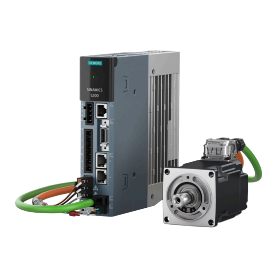
Siemens SINAMICS SIMOTICS S200 PROFINET Manuals
Manuals and User Guides for Siemens SINAMICS SIMOTICS S200 PROFINET. We have
1
Siemens SINAMICS SIMOTICS S200 PROFINET manual available for free PDF download: Operating Instructions Manual
Siemens SINAMICS SIMOTICS S200 PROFINET Operating Instructions Manual (908 pages)
servo drive system
Brand:
Siemens
| Category:
Servo Drives
| Size: 26.97 MB
Table of Contents
Table of Contents
5
Introduction
17
About SINAMICS
17
About this Manual
18
Content
18
Target Group
18
What's New
19
Standard Scope
19
Use of Third-Party Products in this Documentation
20
Websites of Third-Party Companies
20
SINAMICS Documentation
21
Service and Support
22
Siemens Industry Online Support on the Web
22
Spare Parts Services
22
Important Product Information
23
Intended Use
23
Firmware Updates and Constraints
24
Open-Source Software (OSS)
24
Compliance with the General Data Protection Regulation
25
Fundamental Safety Instructions
27
General Safety Instructions
27
Equipment Damage Due to Electric Fields or Electrostatic Discharge
35
Warranty and Liability for Application Examples
36
Cybersecurity Information
37
Residual Risks of Power Drive Systems
38
Description
41
System Overview
41
Converter
45
Motor
46
MOTION-CONNECT 350 and 380 Cables
46
Scope of Delivery
47
Converter
47
Rating Plate
48
Article Number Explanation
49
Serial Number Explanation
50
Motor
50
Rating Plate
52
Article Number Explanation
54
Serial Number Explanation
55
MOTION-CONNECT 350 and 380 Cables
56
Overview
56
Article Number Explanation
57
Device Combinations
58
200 V Servo Drive System
58
400 V Servo Drive System
59
Accessories
61
Connector Kits
61
Cables and Connectors
62
MOTION-CONNECT Cables and Connectors
62
I/O Cable and Connector
64
Line Filter
65
Recommended Line Filters
66
Technical Data
66
Dimension Drawing
67
Mounting Instructions for the Line Filter
71
External 24 V DC Power Supply
72
Replacement Fans
72
Shield Plate Kit
73
SD Card
74
Directives and Standards
75
Directives, Standards and Certificates for the Converter
75
Directives, Standards and Certificates for the Motor
76
Directives, Standards and Certificates for the MOTION-CONNECT Cable
78
Application Planning
81
Protection of Persons from Electromagnetic Fields
81
Fault Protection for the Motor Circuit
83
Permissible Mains Supply Network Configurations for Motors
84
Line Connection Conditions for the Converter with the Motor 1FL2
85
Removing the IT Screw for the Functional Grounding
86
Minimum Cross-Section of the Protective Conductors
88
Electromagnetic Compatibility (EMC)
90
Interference Caused by Electromagnetic Fields
90
EMC Environments in Residential and Industrial Areas
91
EMC Category
91
EMC Limit Values in South Korea
92
Harmonic Current Emissions
92
EMC-Compliant Installation
94
EMC Zones in the Control Cabinet
94
Shielding and Potential Equalization Inside the Control Cabinet
94
Potential Equalization between Control Cabinets
95
Electromechanical Components
95
EMC-Compliant Cable Routing
96
Shielded Cables for the Converter
97
Achievable EMC Category
98
Mounting
101
Converter
101
Mounting Instructions for the Converter
101
Mounting Position
101
Dimension Drawings and Drilling Dimensions
102
Dimension Drawing and Drilling Dimensions for the 200 V Converter
102
Dimension Drawing and Drilling Dimensions for the 400 V Converter
103
Minimum Clearances
104
Motor
105
Transporting and Lifting
105
Checklist Prior to Mounting
108
Safety Labels on the Motor
109
Mounting Instructions for the Motor
110
Mounting Position
112
Dimension Drawings for Motors
113
Dimension Drawing for the 1FL2 Motor, Shaft Height 20
113
Dimension Drawing for the 1FL2 Motor, Shaft Height 30
114
Dimension Drawing for the 1FL2 Motor, Shaft Height 40
115
Dimension Drawing for the 1FL2 Motor, Shaft Height 45
116
Dimension Drawing for the 1FL2 Motor, Shaft Height 48
117
Dimension Drawing for the 1FL2 Motor, Shaft Height 52
118
Dimension Drawing for the 1FL2 Motor, Shaft Height 65
119
Dimension Drawing for the 1FL2 Motor, Shaft Height 90
120
Mounting the Feather Key
121
Attaching Output Elements
122
Laying Cables in Cable Carriers (for MOTION-CONNECT 380 Only)
125
Connecting
129
System Connection
130
Overview of the Converter Interfaces
131
Cables and Connectors
132
Maximum Permissible Cable Lengths
132
Conductor Cross-Sections and Cable Lugs
132
Connecting the Mains Supply
134
Interface Description - X1
134
Wiring
134
Using Several Single-Phase Converters in Machines and Plants
135
Connecting the Motor
137
Routing Cables in Damp Environments
137
Connecting the Motor Power
137
Interface Description - X2 (Converter Side)
137
Interface Description - Power Connector (Motor Side)
138
Wiring
140
Connecting the Motor Holding Brake
141
Interface Description (Converter Side)
141
Interface Description (Motor Side)
141
Wiring
142
Connecting the Encoder
145
Interface Description - X120 (Converter Side)
145
Interface Description (Motor Side)
146
Wiring
147
Rotating the Connectors at the Motor
147
Connecting the Braking Resistor
150
Interface Description - X1
150
Wiring
150
Connecting the 24 V DC Power Supply
153
Interface Description - X124
153
Wiring
153
Connecting the Inputs and Outputs
155
Interface Description - X130
155
Wiring
156
Wiring of Digital Inputs
156
Wiring of Digital Outputs
157
Wiring of Pulse Train Outputs
157
Connecting STO (for S200 PN Only)
159
Interface Description - X131
159
Wiring
159
Connecting to the Fieldbus
161
Interface Description - X150
161
Wiring
162
Connecting the Service Interface (Ethernet)
163
Interface Description - X127
163
Commissioning (Web Server)
165
Introduction
165
Fundamentals
166
Supported Operating Units
166
Requirements for Commissioning
166
Supported Browsers
166
Communication Interfaces
167
Making the Operating Instructions Available for the Web Server Information System
168
Using the Web Server Information System
170
Reloading
173
Getting Started
174
Calling the Web Server
174
Settings for Brand-New Converters
175
Basic Settings
175
Security Settings
176
Functions and Menus
179
Home Page
179
Commissioning
180
Complete Commissioning Workflow
180
Quick Setup
182
Testing the Converter Configuration
185
Optimization
185
Monitoring and Operation
188
Drive Status
188
Inputs/Outputs
190
Diagnostics
190
Messages
190
Diagnostic Buffer
193
Safety Integrated (for S200 PN Only)
194
Connection Overview
195
Communication
195
Status Word and Control Word
197
Parameters
199
Parameter Lists
199
User-Defined Parameter List
201
Backup and Restore
201
Overview
201
Save Drive Data to Backup File
203
Scope of the Backup
203
Restoring Data from an Unencrypted Backup Data
204
Restoring Data from an Encrypted Backup Data
206
Restore Factory Settings
209
System
210
Settings
210
User Management
211
Protection & Security
213
Licenses
215
Firmware Update
217
About Web Server
217
Support
218
Control Panel
219
Commissioning (Startdrive)
221
Introduction
221
Requirements for Commissioning
222
Basics
223
Communication Interfaces
223
Protected Communication
224
User Administration and Security
224
Loading Data from the Drive into the Project
226
Loading Project Data into the Drive
228
Saving Changes in the Project
228
Retentively Saving Changes to the SD Card
229
Using Parameter Lists and User-Defined Lists
230
Procedures for Device Configuration and Commissioning
232
Requirements
232
Simple Basic Parameterization (Offline)
233
Simple Basic Parameterization (Online)
234
Basic Parameterization Together with a SIMATIC Controller
235
Combining and Configuring Devices in the Project
236
Converter
236
Inserting a Converter into the Project
236
Optional: Replacing a Converter
238
Making Detailed Converter Settings
242
Specifying a Motor
243
Control and Technology Object
245
Inserting a SIMATIC S7 Controller into the Project
245
Networking a Controller and a Converter
247
Inserting a Technology Object into the SIMATIC S7 Controller
249
Interconnecting the Technology Object and a Converter
253
Carrying out Guided Quick Startup
255
Overview
255
Editing Mode (Online Only)
258
Connection to PLC
260
Application
261
Limits
262
Configuring Limits When "Speed Control" Is Active
262
Configuring Limits When "Positioning" Is Active
263
Application Settings
267
Configuring Active Homing
268
Configuring Absolute Encoder Adjustment
270
I/O Configuration
272
Telegrams (Offline Only)
273
Rotate & Optimize
275
Overview" Function View
276
Offline Mode
276
Online Mode
277
Configuring the Converter
278
Basic Parameterization
278
Configuring Digital Inputs and Outputs Via Technology Objects
280
Configuring a Measuring Probe Using the Technology Objects
281
Technology Functions
282
Basic Positioner
282
Configuring Pulse Train Output (PTO) (for the S200 Converter Only)
285
Configuring Telegrams
287
Calling the Telegram Configuration
287
Telegram Settings
288
Adding Telegrams
288
Optimizing Commissioning
290
Establishing an Online Connection to the Converter
290
Traversing the Converter from the Control Panel with Speed Setpoint
291
Performing One Button Tuning
293
Terminating the Online Connection from the Converter
295
Using Online Diagnostic Functions
296
Diagnostic Icons
296
Display Messages
296
Calling Diagnostic Functions
298
Security
300
Communication
301
Receive Direction
301
Send Direction
302
Functions
303
Overview
303
Setting the Time-Of-Day
304
Setting the Time with Synchronization (NTP Server)
305
Setting the Time with Synchronization (PLC as NTP Server)
306
Setting the Time Without Synchronization
306
Backup and Restore
307
Restarting the Drive
307
Retentively Saving the Drive Data
308
Restore Factory Settings
308
Overview of Licenses
310
Updating the Firmware in the Startdrive Project
311
Checking Using the Trace Function
313
Series Commissioning
317
Series Commissioning with SD Card
318
Series Commissioning Using the Web Server
319
Functions
321
Overview of the Functions
321
Inputs/Outputs
323
Digital Inputs
323
Digital Outputs
324
Fieldbus Communication
327
Communication Via PROFINET IO
327
Configuring PROFINET IO Operation
327
Connecting the PROFINET Cable to the Converter
327
Configuring Communication Using SIMATIC S7 Control
328
Setting Communication Via PROFINET
328
PROFINET Protocols
329
Media Redundancy
330
Connection-Oriented Communication Protocols
331
Identification & Maintenance (I&M) Data
332
Communication Telegrams
334
Telegram Structure
334
Supported Telegrams
335
Telegrams for Speed Control
335
Telegram 1
335
Telegram 2
336
Telegram 3
337
Telegram 5
338
Telegram 102
339
Telegram 105
340
Telegrams for Position Control
340
Telegram 7
340
Telegram 9
341
Telegram 111
342
Telegram 112
343
Supplementary Telegram
344
Control Words, Status Words and Message Word
344
Control and Status Word 1
344
Control and Status Word 2
349
Control and Status Word for Encoder 1
351
Control Word for Block Selection
352
Control Word for MDI Mode
353
Control and Status Word 1 for the Positioner
354
Control and Status Word 2 for the Positioner
356
Message Word
358
General Functions
359
Stopping Method at Servo-Off
359
Speed Limit
360
Torque Limit
362
Vertical Axis
363
PTO Function (for S200 PN Only)
364
Ramp-Function Generator
366
Setting Motor Overload Protection in Accordance with UL 61800-5-1 Ed.2
369
Basic Positioner (EPOS)
370
Mechanical System
371
Axis Type
371
Units of Measurement
372
Setting the Backlash
373
Limits
375
Limiting the Traversing Range
375
Limiting the Traversing Profiles
376
Position Monitoring
376
Positioning and Standstill Monitoring
376
Following Error Monitoring
377
Homing
378
Terms for Homing
379
Active Homing
380
Passive Homing
383
Absolute Encoder Adjustment
384
Setting the Home Position
385
Traversing Blocks
385
Traversing Block Tasks
385
Travel to Fixed Stop
391
Direct Setpoint Input (MDI)
392
Jog
396
Measuring Probe Evaluation and Homing Mark Search
398
Safety Integrated (for S200 PN Only)
400
Safety Integrated Functions
401
Certification
402
PFH Values
402
Usage Time
403
Stop Functions
403
Safe Torque off (STO)
403
Functional Features of STO
405
Discrepancy Time
406
Input Filter
407
Self-Test of the Fail-Safe Digital Input (F-DI)
407
Safety Integrated Function Status/Diagnostics
408
Responses to Safety Messages
408
Stop Responses
408
Fail-Safe Acknowledgement of Safety Messages
409
Response Time
410
Functional Safety
410
Machinery Directive
411
Tuning
413
Tuning Workflow
413
Autotuning
414
One Button Tuning
414
Real Time Tuning (Online Tuning)
415
Manual Tuning
417
Control Loops
417
Servo Gain Adjustment
418
Resonance Suppression
420
System Messages
423
SDI Status
423
SDI Status Overview
423
Status Display Via Leds
424
SDI Status Display
426
Function Buttons
428
System Runtime
429
Faults and Alarms
430
Overview of Faults and Alarms
430
Faults
431
Alarms
432
Explanation of the List of Faults and Alarms
432
List of Fault Codes and Alarm Codes
438
Corrective Maintenance
589
Service and Maintenance for the Converter
589
Restoring the Converter to Factory Settings
589
Restoring Factory Settings Via a Commissioning Tool
589
Reset of All User-Defined Settings to the Factory Setting Via an SD Card
589
Converter Firmware Update
591
Overview of Firmware Update
591
Firmware Update Via an SD Card
591
Replacing the Converter
592
Restoring the Drive Data Via the Web Server
595
Restoring Data from an Unencrypted Backup File
596
Restoring Data from an Encrypted Backup File
598
Forming the DC Link Capacitors
600
Service and Maintenance for the Motor
602
Replacing the Motor Bearings
604
Replacing the Motor
605
Service and Maintenance for Spare Parts
607
Spare Parts and Spare Parts Compatibility
607
Replacing the Fan Unit (400 V Converters FSC and FSD Only)
607
Advertisement
Advertisement
Related Products
Siemens SINAMICS/SIMOTICS S200
Siemens SINAMICS S210
Siemens SIMOTICS S-1FK2
Siemens SINAMIC S120
Siemens SIMATIC MICRO-DRIVE
Siemens SINAMICS S200
Siemens SIMOTICS S-1FL2
Siemens SINAMICS S150
Siemens SINAMICS Series
Siemens Sinamics Connect Series
Siemens Categories
Industrial Equipment
Controller
Control Unit
Oven
Washer
More Siemens Manuals
Login
Sign In
OR
Sign in with Facebook
Sign in with Google
Upload manual
Upload from disk
Upload from URL