Sign In
Upload
Manuals
Brands
Sony Manuals
Receiver
HCD-FX100W
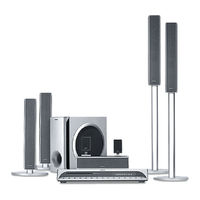
Sony HCD-FX100W Manuals
Manuals and User Guides for Sony HCD-FX100W. We have
2
Sony HCD-FX100W manuals available for free PDF download: Service Manual
Sony HCD-FX100W Service Manual (212 pages)
Brand:
Sony
| Category:
Home Theater System
| Size: 18.6 MB
Table of Contents
Table of Contents
94
Servicing Note
95
General
96
Disassembly
98
Disassembly Flow
98
Top Panel Sub Assy
99
Front Panel Assy
100
I/O Board, DC Fan
100
MIB01 Board, MIB01 POWER Board
101
DMB10 Board, TX Board
102
MAIN Board, H/P Board
103
FL Board, KEY Board, LED Board
103
DVD Mechanism Deck (CDM69EH-DVBU101)
104
Base Unit (DVBU101)
104
Optical Pick-Up (KHM-310CAB/C2NP)
105
SW Board, Bracket (Top) Assy
105
RELAY Board
106
Motor (Stocker) Assy (Stocker)(M761)
106
Motor (Roller) Assy (Roller)(M781)
107
Motor (Mode) Assy (Mode)(M771)
107
Rubber Roller (Slider) ASSY
108
Timing Belt (Front/Rear)
108
Cam (Gear)
109
SENSOR Board
109
Assembly
110
How to Install the Cam (Eject Lock)
110
How to Install the Cam (Gear)
110
How to Install the Gear (Mode C)
111
How to Install the Gear (Mode Cam)
111
How to Install the Rotary Encorder (S702), Gear (Stocker Communication)
112
How to Install the Stocker Assy
112
Test Mode
113
Electrical Adjustment
117
Block Diagram - RF Section
120
MIB Section
121
VIDEO Section
122
AMP Section
123
AUDIO Section
124
MAIN Section
125
DIAT TRANSMIT Section
126
Printed Wiring Board - CHANGER Section
127
Schematic Diagram - CHANGER Section
128
Printed Wiring Board - DMB10 Section (Side A)
129
Printed Wiring Board - DMB10 Section (Side B)
130
Schematic Diagram - DMB10 Section (1/4)
131
Schematic Diagram - DMB10 Section (2/4)
132
Schematic Diagram - DMB10 Section (3/4)
133
Schematic Diagram - DMB10 Section (4/4)
134
Printed Wiring Board - MAIN Section (Side A)
135
Printed Wiring Board - MAIN Section (Side B)
136
Schematic Diagram - MAIN Section (1/8)
137
Schematic Diagram - MAIN Section (2/8)
138
Schematic Diagram - MAIN Section (3/8)
139
Schematic Diagram - MAIN Section (4/8)
140
Schematic Diagram - MAIN Section (5/8)
141
Schematic Diagram - MAIN Section (6/8)
142
Schematic Diagram - MAIN Section (7/8)
143
Schematic Diagram - MAIN Section (8/8)
144
Printed Wiring Board - FL/KEY Section
145
Schematic Diagram - FL/KEY Section
146
Printed Wiring Board - LED / H/P Section
147
Schematic Diagram - LED / H/P Section
148
Printed Wiring Board - I/O Section (Side A)
149
Printed Wiring Board - I/O Section (Side B)
150
Schematic Diagram - I/O Section
151
Printed Wiring Board - MIB01 Section (Side A)
152
Printed Wiring Board - MIB01 Section (Side B)
153
Schematic Diagram - MIB01 Section (1/3)
154
Schematic Diagram - MIB01 Section (2/3)
155
Schematic Diagram - MIB01 Section (3/3)
156
Printed Wiring Board - MIB01 POWER Section
157
Schematic Diagram - MIB01 POWER Section
157
Printed Wiring Board - TX Section
158
Schematic Diagram - TX Section
159
Exploded Views
180
Overall Section
180
Front Panel Assy Section
181
Chassis Section-1
182
Chassis Section-2
183
DVD Mechanism Deck Section-1 (CDM69EH-DVBU101)
184
DVD Mechanism Deck Section-2 (CDM69EH-DVBU101)
185
DVD Mechanism Deck Section-3 (CDM69EH-DVBU101)
186
DVD Mechanism Deck Section-4 (CDM69EH-DVBU101)
187
DVD Mechanism Deck Section-5 (CDM69EH-DVBU101)
188
DVD Mechanism Deck Section-6 (CDM69EH-DVBU101)
189
Optical Pick-Up Section (KHM-310CAB/C2NP)
190
Electrical Parts List
191
Advertisement
Sony HCD-FX100W Service Manual (122 pages)
Brand:
Sony
| Category:
Receiver
| Size: 22.31 MB
Table of Contents
Service Manual
1
Table of Contents
4
1 Servicing Note
5
2 General
6
3 Disassembly
8
Disassembly Flow
8
Top Panel Sub Assy
9
Front Panel Assy
10
I/O Board, DC Fan
10
MIB01 Board, MIB01 POWER Board
11
DMB10 Board, TX Board
12
MAIN Board, H/P Board
13
FL Board, KEY Board, LED Board
13
DVD Mechanism Deck (CDM69EH-DVBU101)
14
Base Unit (DVBU101)
14
Optical Pick-Up (KHM-310CAB/C2NP)
15
SW Board, Bracket (Top) Assy
15
RELAY Board
16
Motor (Stocker) Assy (Stocker)(M761)
16
Motor (Roller) Assy (Roller)(M781)
17
Motor (Mode) Assy (Mode)(M771)
17
Rubber Roller (Slider) ASSY
18
Timing Belt (Front/Rear)
18
Cam (Gear)
19
SENSOR Board
19
4 Assembly
20
How to Install the Cam (Eject Lock)
20
How to Install the Cam (Gear)
20
Tel 13942296513
20
How to Install the Gear (Mode C)
21
How to Install the Gear (Mode Cam)
21
How to Install the Rotary Encorder (S702)
22
Gear (Stocker Communication)
22
How to Install the Stocker Assy
22
5 Test Mode
23
6 Electrical Adjustment
27
7 Diagrams
29
Block Diagram - RF Section
30
MIB Section
31
VIDEO Section
32
AMP Section
33
AUDIO Section
34
MAIN Section
35
DIAT TRANSMIT Section
36
Printed Wiring Board - CHANGER Section
37
Schematic Diagram - CHANGER Section
38
Printed Wiring Board - DMB10 Section (Side A)
39
Printed Wiring Board - DMB10 Section (Side B)
40
Schematic Diagram - DMB10 Section (1/4)
41
Schematic Diagram - DMB10 Section (2/4)
42
Schematic Diagram - DMB10 Section (3/4)
43
Schematic Diagram - DMB10 Section (4/4)
44
Printed Wiring Board - MAIN Section (Side A)
45
Printed Wiring Board - MAIN Section (Side B)
46
Schematic Diagram - MAIN Section (1/8)
47
Schematic Diagram - MAIN Section (2/8)
48
Schematic Diagram - MAIN Section (3/8)
49
Schematic Diagram - MAIN Section (4/8)
50
Schematic Diagram - MAIN Section (5/8)
51
Schematic Diagram - MAIN Section (6/8)
52
Schematic Diagram - MAIN Section (7/8)
53
Schematic Diagram - MAIN Section (8/8)
54
Printed Wiring Board - FL/KEY Section
55
Schematic Diagram - FL/KEY Section
56
Printed Wiring Board - LED / H/P Section
57
Schematic Diagram - LED / H/P Section
58
Printed Wiring Board - I/O Section (Side A)
59
Printed Wiring Board - I/O Section (Side B)
60
Schematic Diagram - I/O Section
61
Printed Wiring Board - MIB01 Section (Side A)
62
Printed Wiring Board - MIB01 Section (Side B)
63
Schematic Diagram - MIB01 Section (1/3)
64
Schematic Diagram - MIB01 Section (2/3)
65
Schematic Diagram - MIB01 Section (3/3)
66
Printed Wiring Board - MIB01 POWER Section
67
Q Q 7-33. Schematic Diagram - MIB01 POWER Section
67
Printed Wiring Board - TX Section
68
Schematic Diagram - TX Section
69
8 Exploded Views
90
Overall Section
90
Front Panel Assy Section
91
Chassis Section-1
92
Chassis Section-2
93
DVD Mechanism Deck Section-1 (CDM69EH-DVBU101)
94
DVD Mechanism Deck Section-2 (CDM69EH-DVBU101)
95
DVD Mechanism Deck Section-3 (CDM69EH-DVBU101)
96
DVD Mechanism Deck Section-4 (CDM69EH-DVBU101)
97
DVD Mechanism Deck Section-5 (CDM69EH-DVBU101)
98
DVD Mechanism Deck Section-6 (CDM69EH-DVBU101)
99
Optical Pick-Up Section (KHM-310CAB/C2NP)
100
9 Electrical Parts List
101
Advertisement
Related Products
Sony HCD-FX900W
Sony HCD-FX1000W
Sony HCD-FX999W
Sony HCD-FX888K
Sony HCD-FX200
Sony HCD-FX205
Sony HCD-FX900KW
Sony HCD-FLX7D
Sony HCD-FR9
Sony HCD-FZ900M
Sony Categories
Laptop
TV
CD Player
Camcorder
Digital Camera
More Sony Manuals
Login
Sign In
OR
Sign in with Facebook
Sign in with Google
Upload manual
Upload from disk
Upload from URL