Sign In
Upload
Manuals
Brands
Toshiba Manuals
Network Card
RemotEye 4
Toshiba RemotEye 4 UPS Network Card Manuals
Manuals and User Guides for Toshiba RemotEye 4 UPS Network Card. We have
2
Toshiba RemotEye 4 UPS Network Card manuals available for free PDF download: User Manual, Procedure For Installing
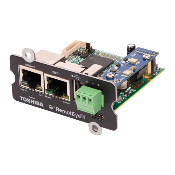
Toshiba RemotEye 4 User Manual (262 pages)
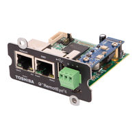
4 UPS Network Card
Brand:
Toshiba
| Category:
Network Card
| Size: 12.03 MB
Table of Contents
About this Manual
2
Contacting Toshiba's Customer Support Center
3
Important Notice
3
Important Safety Instructions
3
Table of Contents
5
List of Figures
9
List of Tables
11
1 General Safety Instructions
13
Safety Alert Symbols
13
Special Symbols
13
Electrical Hazard Symbol
13
Explosion Hazard Symbol
14
Equipment Warning Labels
14
Installation Precautions
14
2 Introduction
15
Purpose & Manual Overview
15
Applicable Specifications
15
Ups Compatibility
16
Package Contents
16
Remoteye 4 Layout and Led Indicators
17
Figure 2-1 Remoteye 4 Faceplate Layout
17
Table 2-1 Remoteye 4 Connections
17
Hard Reset Button
18
Figure 2-2 Remoteye 4 Hard Reset Button Access
18
Figure 2-3 Remoteye LED Locations
19
Table 2-2 Remoteye 4 LED Indications
19
Features
20
HTTP Web Access
20
SNMP Access
20
Figure 2-4 HTTP Web Access Dashboard Example
20
Bacnet and Modbus Access
21
Additional Features
21
Figure 2-5 *** SNMP Access to Remoteye 4
21
Remoteye 4 Support Software Programs
22
Optional - Environmental Monitoring Device (EMD)
22
Optional - Remoteye Sensor Pack for EMD
23
Optional - Remotradar Software
23
Figure 2-6 EMD Module
23
Figure 2-7 EMD Sensor Pack
23
3 Setup
24
Checklist
24
Figure 2-8: Remotradar Example
24
Table 3-1 Set-Up Checklist
24
Install Remoteye 4 in Ups
25
Figure 3-1 Remoteye 4 MAC Address Location
25
Figure 3-2 Remoteye 4 Location in 1600XP
25
Figure 3-3 Remoteye 4 in 4300 and 4400 UPS
26
Figure 3-4 Remoteye 4 in G9000/G2020 UPS
26
Figure 3-5 Remoteye 4 in G9000 1000Kva
27
4 Remoteye 4 Network Connection Setup
31
Ip Address Setup with Dhcp
31
Table 4-1 Monitoring Protocol and Port Connector
31
Ip Address Setup with Custom Network Settings
32
Install USB Driver (Windows 8.1)
32
Figure 4-1 Remoteye 4 Network Connection Example
32
Install USB Driver (Windows 7)
33
Establishing Comminication
33
Figure 4-2 PC to Remoteye 4 USB-Mini-USB Cable Adapter
33
Set the IP Address
34
Figure 4-3 Tera Term Opening Screen
34
Figure 4-4 Serial Port Setup
34
Figure 4-5 Remoteye 4 Configuration Utility Main Menu
35
5 System Configuration Via Web Interface
36
Software Setup
36
First Time Setup
36
Figure 5-1 Login Screen
36
Figure 5-2 First Time Setup Screen
36
Figure 5-3 Login/Guest Mode Settings
37
Figure 5-4 First Time Setup Screen
38
Dashboard (Home Page) Layout
39
Figure 5-5 Remoteye 4 Default Dashboard (Home Page) Layout
39
Figure 5-6 Default UPS Pictures
40
Figure 5-7 Remote View Flow Diagrams (RVFD)
41
Figure 5-8 Dynamic (Comprehensive) Block by Series
41
Customizing the Dashboard Layout
42
Figure 5-10 Login to Edit Dashboard
42
Figure 5-11 Edit Dashboard Button
42
Figure 5-9 History/Trend Blocks
42
Figure 5-12 Edit Dashboard Mode
43
Figure 5-13 Edit Dashboard Mode - Drop-Down Menu
44
Web Navigation
44
UPS MONITORING Drop-Down Menu
45
Figure 5-14 Drop-Down Menus
45
Figure 5-15 SETTINGS Web Page
45
UPS MANAGEMENT Drop-Down Menu
46
SETTTINGS Drop-Down Menu
46
EMD Drop-Down Menu
46
Username} Drop-Down Menu
46
6 Protocol Setup
47
Snmp Setup
47
Figure 6-1 SNMP Settings Panel
47
Toshiba MIB Files
48
NMS (Manager) Settings
48
Modbus Tcp/Ip or Bacnet Ip Setup
48
Configure for Modbus TCP/IP
48
Configure for Bacnet IP
49
Figure 6-2 Modbus TCP/IP and Bacnet IP Configuration Panels
49
Modbus Rtu or Bacnet Ms/Tp Setup
50
Configure for Modbus RTU
50
Figure 6-3 Remoteye 4 RS-485 Data and GND Cabling
50
Figure 6-4 Interface Settings for Modbus RTU
50
Figure 6-5 Modbus Settings for Modbus RTU
51
Figure 6-6 Modbus Read/Write Definitions
51
Configure for Bacnet MS/TP
52
Figure 6-7 Example - Modbus Poll for 1600XP
52
Figure 6-8 Remoteye 4 RS-485 Data and GND Cabling
53
Figure 6-9 Interface Settings for Bacnet MS/TP
53
Figure 6-10 Bacnet Settings for Bacnet MS/TP
54
7 Optional Features Setup
55
Radius Configuration
55
Email Notification
55
Table 7-1 Daily/Event Status Logs
56
Reminders
57
Wireless System Settings
57
Remoteye 4 System Settings
57
Figure 7-1 Wireless System Settings View
57
Emd (Environmental Monitoring Device)
58
EMD Installation
59
EMD Parameters
59
Table 7-2 EMD Layout and Indicators
59
EMD Configuration
60
8 Mobile-Friendly Web Interface
61
Display and Navigation
61
Figure 8-1 Mobile Webpage by Product Line
61
Alert Center
62
Protected Clients
62
Figure 8-2 Input Parameters Mobile Webpage - by Product Line
62
Figure 8-3 Example of Alert Center and Protected Clients
62
9 Remoteye 4 Console Menu Navigation
63
Table 9-1 Console Menu Tree
63
Main Menu Description
66
Figure 9-1 Remoteye 4 Console Main Menu
66
Remoteye 4 Card Settings
67
Figure 9-2 Remoteye 4 Card Settings Menu
67
IP, Time and System Group
68
Figure 9-3 IP, Time and System Group Menu
68
Figure 9-4 Ipv4 Group Menu
69
Figure 9-5 Ipv6 Group Menu
69
Network Control Group
70
Figure 9-6 Date and Time Group Menu
70
Figure 9-7 Network Control Group Menu
71
Figure 9-8 SNMP Control Group
71
Figure 9-9 SMTP Control Group
72
Figure 9-10 SSH Control Group
72
Figure 9-11 Telnet Control Group
72
Account Control Group
73
Figure 9-12 HTTP Control Group
73
Figure 9-13 Configuration Control Group Menu
73
Figure 9-14 RADIUS Group Menu
74
Figure 9-15 Access Control Table
74
Email Group
75
Figure 9-16 Super User Group Menu
75
Figure 9-17 Email Group Menu
76
Figure 9-18 Mail Receiver Table
76
SNMP Group
77
Figure 9-19 SNMP Group Menu
77
Figure 9-20 Trap Receiver Table
77
Modbus Group
78
Figure 9-21 Snmpv3 USM Table
78
Bacnet Group
79
Interface Settings Group
79
Figure 9-22 Modbus Group Menu
79
Figure 9-23 Bacnet Group Menu
79
Figure 9-24 Interface Settings Group Menu
80
Figure 9-25 Reset Configuration to Default
80
Figure 9-26 Restart SNMP/WEB Card
80
Reset Configuration to Default
80
Restart Remoteye Card
80
10 History Data & Logs
81
Ups History Summary Summary Page
81
Table 10-1 History Log Availability
81
Table 10-2 UPS History Summary Page Availability
81
General Records Page
82
Extended General Records Page
82
Test Records (T1000 & 1600Xp/Xpi Only)
83
Backup Records Page
83
Fault Records Page
84
Operation Mode Records Page
86
Warning Records Page
87
System Settings Change Records Page (T1000 & 1600Xp/Xpi Only)
89
Ups Events Records Page
89
Remoteye 4 Events Records Page
89
Table 10-4 Remoteye 4 UPS Warning Codes
89
Acknowledged Alerts Records Page
90
Emd History Log
90
Emd Extended History Log
90
11 Remoteye Application Programs
91
Remoteye Client Shutdown Software for Esxi 5/5.1/5.5/6.0
91
Software Needed
91
Figure 11-1 Network with Remoteye and Esxi Servers
91
Setup Procedure for Remoteye Esxi Client Shutdown Daemon
92
Figure 11-2 Text Turns RED in Super User Mode
92
Figure 11-3 Add Server to Vma
92
Figure 11-4 Esxi Added to VMA
92
Figure 11-5 Winscp Login Screen
93
Figure 11-6 Winscp VI-Admin Screen
94
Figure 11-7 Install Screen Shot
95
Figure 11-8 Protected Client Table in Remoteye
95
Figure 11-9 Vsphere Management Asistant Screen Shot
96
Figure 11-10 VM Remote Shutdown Test
97
Toshiba UPS Shutdown Events Setup
98
Auto Save-Log Software
100
Figure 11-11 Remoteye 4 Save Log Utility Remoteye 4 - Auto Save Log Tab
100
Selecting
101
Device List
101
Figure 11-12 Remoteye 4 Save Log Utility Remoteye 4 - Selecting
101
Figure 11-13 Remoteye 4 Save Log Utility - Device List
101
Status
102
Save Log Settings
102
Figure 11-14 Remoteye 4 Save Log Utility - Status
102
Figure 11-15 Remoteye 4 Save Log - Settings
102
Figure 11-16 Remoteye 4 Save Log - Set Page
103
Remote Config Tool
103
Tupgrade - Firmware Tool
104
General Information
104
Figure 11-17 Remote Config Tool - Detail
104
Figure 11-18 Tupgrade Utility Opening Display
105
Table 11-1 Tupgrade Toolbar Functions
105
Hardware Setup
106
12 Specifications
106
System Specifications
106
Table 12-1 Remoteye 4 System Specifications
106
Led Indicators Key
107
Table 12-2 Remoteye 4 LED Indications
107
Firmware Specifications
108
Pcb Gold Finger (Gf1)
108
Network Connector (J2)
108
Rs-232/Emd Cabling Key (J3)
108
Figure 12-1 PCB Top View/Goldfinger
108
Table 12-3 Firmware Specifications
108
Table 12-4 Pin-Outs for Network RJ-45
108
Table 12-5 Pin-Outs for RS-232/EDM RJ-45
108
Rs-485 Cabling Key
109
Figure 12-2 Remoteye 4 Faceplate
109
Table 12-6 Pin-Outs for RS-485 (Phoenix) Connector
109
Appendix A - Modbus Registers for All Ups
110
Modbus (3X) Input Registers for G9000/G2020 Series Ups: Monitoring
110
Modbus (3X) Input Registers for 4300, 4400, and 5000 Series Ups: Monitoring
121
Modbus (3X) Input Registers for Single Phase Ups: Monitoring
131
Modbus (1X) Input Registers for Three Phase Ups: Alarms and Status
143
Modbus (1X) Input Registers for Single Phase Ups: Alarms and Status
152
Appendix B - Bacnet Point Mapping for 1600Xp/Xpi
163
Bacnet Analog Input Point Mapping for 1600Xp/Xpi
163
Bacnet Binary Input Point Mapping for 1600Xp/Xpi
167
Appendix C - Bacnet Point Mapping for 4300
171
Bacnet Analog Input Point Mapping for 4300
171
Bacnet Binary Input Point Mapping for 4300
174
Appendix D - Bacnet Point Mapping for 4400
178
Bacnet Analog Input Point Mapping for 4400
178
Bacnet Binary Input Point Mapping for 4400
182
Appendix E - Bacnet Point Mapping for G9000/G2020
187
Bacnet Analog Input Point Mapping for G9000/G2020
187
Bacnet Binary Input Point Mapping for G9000/G2020
190
Appendix F- Bacnet Point Mapping for 5000 Nema 3R
192
Bacnet Analog Input Point Mapping for 5000 Nema 3R
192
Bacnet Binary Input Point Mapping for 5000 Nema 3R
196
Appendix G- Bacnet Point Mapping for T1000
200
Bacnet Analog Input Point Mapping for T1000
200
Bacnet Binary Input Point Mapping for T1000
203
Appendix H - - Bacnet Point Mapping for T1000 (1-3Kva)
206
Bacnet Analog Input Point Mapping for T1000 (1-3Kva)
206
Bacnet Binary Input Point Mapping for T1000 (1-3Kva)
208
Appendix I - - Bacnet Point Mapping for 5000 (3P1)
210
Bacnet Analog Input Point Mapping for 5000 (3P1)
210
Bacnet Binary Input Point Mapping for 5000 (3P1)
213
Appendix J - - Bacnet Point Mapping for G9000/G2020 V2
216
Bacnet Analog Input Point Mapping for G9000/G2020 V2
216
Bacnet Binary Input Point Mapping for G9000/G2020 V2
219
Appendix K - Snmp Mib Oid's for 1600Xp/Xpi
222
Appendix L - Snmp Mib Oid's for 4300
228
Appendix M - Snmp Mib Oid's for 4400
233
Appendix N - Snmp Mib Oid's for G9000/G2020
238
Appendix O - Snmp Mib Oid's for 5000 Nema 3R
241
Appendix P - Snmp Mib Oid's for T1000
246
Appendix Q - Snmp Mib Oid's for T1000 (1-3 Kva)
250
Appendix R - Snmp Mib Oid's for 5000 (3P1)
252
Appendix S - Snmp Mib Oid's for G9000/G2020 V2
256
Appendix T - Additional Rs-485 Connection Information
260
Advertisement
Toshiba RemotEye 4 Procedure For Installing (8 pages)
on G9000 Series UPS (Pre-Installed Brackets)
Brand:
Toshiba
| Category:
Measuring Instruments
| Size: 1 MB
Advertisement
Related Products
Toshiba RemoteEye II
Toshiba RemotEye III
Toshiba Rockbox F Series
Toshiba RemotEye II
Toshiba RemotEye ESS
Toshiba REGZA SL Series with Freeview HD
Toshiba Regza46RV535U
Toshiba REGZA XV Digital Series
Toshiba Regza 37HL17 Regza 42HL17
Toshiba REGZA RV Digital Series
Toshiba Categories
Laptop
Air Conditioner
TV
LCD TV
All in One Printer
More Toshiba Manuals
Login
Sign In
OR
Sign in with Facebook
Sign in with Google
Upload manual
Upload from disk
Upload from URL