Sign In
Upload
Manuals
Brands
Toshiba Manuals
Laptop
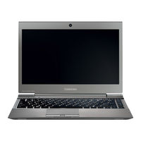
Satellite Z930
Toshiba Satellite Z930 Manuals
Manuals and User Guides for Toshiba Satellite Z930. We have
1
Toshiba Satellite Z930 manual available for free PDF download: Maintenance Manual
Toshiba Satellite Z930 Maintenance Manual (424 pages)
Personal Computer
Brand:
Toshiba
| Category:
Laptop
| Size: 10.19 MB
Table of Contents
Safety Precautions
3
Acronyms
5
Conventions
5
Key Operation
5
Keys
5
Table of Contents
6
Table of Contents
9
Chapter 1 Hardware Overview
11
Contents
13
Features
15
Bluetooth
18
Internal LAN
18
Web Camera
18
Wireless LAN
18
Figure 1-1 Front of the Computer
19
Figure 1-2 System Unit Configurations
20
Figure 1-3 System Unit Block Diagram
21
3.5-Inch Floppy Disk Drive (USB External)
26
Figure 1-4 3.5-Inch FDD (USB External)
26
Table 1-1 3.5-Inch FDD Specifications
26
Figure 1- 5 Msata SSD
27
Msata SSD
27
Table 1-2 Msata SSD Specifications
27
Keyboard
28
Figure 1- 7 LCD Module
29
Table 1-3 LCD Module Specifications
29
TFT Color Display
29
Power Supply
30
Table 1-4 Power Supply Output Rating
31
Batteries
32
Battery Specifications
32
Main Battery
32
Table 1-5 Battery Specifications
32
Battery Charging Control
33
Table 1-6 Time Required for Charges
33
Table 1-7 Data Preservation Time
34
Table 1-8 RTC Battery Charging/Data Preservation Time
34
AC Adapter
35
Table 1-9 AC Adapter Specifications
35
Chapter 2 Troubleshooting Procedures
37
Troubleshooting
42
Troubleshooting Flowchart
44
Power Supply Troubleshooting
49
Procedure 1 Power Status Check
49
Battery Icon
49
Procedure 2 Error Code Check
49
Procedure 3 Connection Check
49
DC in Icon
50
Procedure 2 Error Code Check
51
DC Power Supply (AC Adapter)
52
Error Code
52
Main Battery
53
Procedure 3 Connection Check
55
Ptv Output
55
Procedure 4 Charging Check
57
Procedure 5 Replacement Check
57
When AC Adapter Is Connected
57
When AC Adapter Is Not Connected
57
System Board Troubleshooting
58
Procedure 1 Message Check
59
A Set of Tool for Debug Port Test
61
Procedure 2 Debugging Port Check
61
Procedure 3 Diagnostic Test Program Execution Check
67
Procedure 4 Replacement Check
67
Procedure 1 FDD Head Cleaning Check
68
USB FDD Troubleshooting
68
FDD Error Code and Status
69
Procedure 2 Diagnostic Test Program Execution Check
69
Procedure 3 Connector Check and Replacement Check
70
Msata SSD Troubleshooting
72
Note: Partition Check Cannot be Performed in Diagnostics Disk (CD)
72
Procedure 1 Partition Check (Not Used)
72
Procedure 2 Message Check
73
Procedure 3 Format Check (Not Used)
74
Procedure 4 Diagnostic Test Program Execution Check
75
Procedure 5 Connector Check and Replacement Check
76
Keyboard Troubleshooting
77
Procedure 1 Diagnostic Test Program (And Windows)Execution Check
77
Procedure 2 Connector Check and Replacement Check
77
Procedure 1 Diagnostic Test Program Execution Check
79
Procedure 2 Connector Check and Replacement Check
79
Touch Pad Troubleshooting
79
Connector Check and Cable Check
81
Diagnostic Test Program Execution Check
81
Display Troubleshooting
81
Replacement Check
82
LAN Troubleshooting
83
Procedure 1 Diagnostic Test Program Execution Check
83
Procedure 2 Connector Check and Replacement Check
83
Procedure 1 Transmitting-Receiving Check
85
Procedure 2 Antennas' Connection Check
85
Wireless LAN or Wireless LAN +Bluetooth Troubleshooting
85
Procedure 3 Replacement Check
86
Procedure 1 Diagnostic Test Program Execution Check
87
Procedure 2 Connector Check
87
Sound Troubleshooting
87
Procedure 3 Replacement Check
88
Memory Media (SD Card) Slot Troubleshooting
89
Procedure 1 Check on Windows os
89
Procedure 2 Connector Check and Replacement Check
89
Fingerprint Sensor Troubleshooting
90
Registration of Fingerprint
91
Setting Windows Log-ON Password
91
Authentication of Fingerprint
92
Connector Check and Replacement Check
93
Procedure 1 Check on Windows os
95
Web Camera Troubleshooting
95
Procedure 2 Connector Check and Replacement Check
96
Troubleshooting
97
Connecting the HDMI out Port
99
HDMI Troubleshooting
99
Procedure 1 Check on HDMI TV
99
Settings for Display Video on HDMI
100
Select HD Format
101
Chapter 3 Tests and Diagnostics
103
The Diagnostic Test
109
H/W (Hardware) Initial Information Setting Tool
111
Heatrun Test Program
111
Executing the Diagnostic Test
112
The Check and Update of EC/KBC Information
113
Diagnostics Menu (T&D)
115
H/W Initial Information Setting Tool
118
Heatrun Test Program
118
Entry of the DMI Information
119
Setting of the Hardware Configuration
119
DMI Information Recovery
120
DMI Information Save
120
Heatrun Test
121
Figure 1- 6 Keyboard
122
Subtest Names
122
System Test
124
Keyboard Test
127
Pressed Key Code Display
127
Display Test
128
Gradation for LCD
128
Gradation for VGA
128
VRAM Read/Write for VGA
128
All Dot On/Off for LCD
129
Gradation & Mode Test for VGA
129
LCD Brightness
130
“H” Pattern Display
130
Floppy Disk Test
131
Random Address/Data
132
Sequential Read
132
Sequential Read/Write
132
Write Specified Address
132
Printer Test
133
Ripple Pattern
133
Wraparound
134
Async Test
135
FIR/SIR Point to Point (Receive)
135
FIR/SIR Point to Point (Send)
135
Wraparound (Board)
135
Hard Disk Test
136
Address Uniqueness
137
Cross Talk & Peak Shift
138
Partial Read
138
Backup Memory
139
Real Timer Test
139
Real Time Carry
140
NDP Test
141
Expansion Test
142
RGB Monitor ID
143
CD-ROM/DVD-ROM Test
144
Error Code and Error Status Names
145
Hard Disk Controller Status Register Contents
148
Hard Disk Test Detail Status
148
HDC Error Register Contents
149
Only One Test
150
Operations
150
Program Description
150
Pressed Key Display (Main Key)
151
Touch Pad /IPS
152
USB Port Select Menu
153
Led
154
Fan Control
156
Press Function Button (TOSHIBA Eco Button)
156
Press Function Button (TOSHIBA Presentation Button)
156
Usb 3.0
157
Function Description
158
Head Cleaning
158
Operations
158
Function Description
159
Log Utilities
159
Operations
160
Function Description
161
Operations
161
Running Test
161
Floppy Disk Drive Utilities
162
Format
162
Function Description
162
FORMAT Program
163
Operations
163
COPY Program
164
DUMP Program
165
HDD ID READ Program
166
Utilities Menu
166
Function Description
167
System Configuration
167
Operations
168
Check of the Wireless LAN Card Type
169
Wireless LAN Test Program (Atheros)
169
Check of the Antenna Connection
170
Configuration of Equipment for Transmitting-Receiving Test
171
How to Setup the REF PC
171
Wireless LAN Test Program (Intel-Made A/B/G/N Setting up of REF PC)
171
Screen While Running the Wtwinsvr Program
175
Startup Screen of Wtwinsvr Program
175
Wireless LAN Test Program on DUT PC (Intel-Made)
176
LAN Test
180
Lan/Modem/Bluetooth/Ieee1394 Test Program
180
Modem Test : (Not Used)
183
Bluetooth Test
184
IEEE1394 Test (Not Used)
186
Sound Test Program
187
Function Description
188
Main Menu
188
Security Menu
188
Setup
188
Advanced Menu
189
Power Management Menu
189
Exit Menu
190
Accessing the SETUP Program
191
Main Menu Screen
191
Power Management Menu Screen
192
Security Menu Screen
192
Advanced Menu Screen
193
Exit Menu Screen
193
Accepting Changes and Exiting the SETUP Window
194
Moving Within the SETUP Menu and Changing Values
194
The Factory Preset Configuration
194
How to Change Setup Options
195
Maintenance (Winpe&Freedos) Test Program Operation
196
Outline of Specification
196
Outline of Freedos T&D
196
Starting TOSHIBA Test & Diagnostic
197
Equipment Configuration for Test
199
Windows PE T&D
199
Starting T&D
200
Automatic Start
200
Manual Start
200
System Information Menu
201
Explanation of each Item
201
Details of the System Information Displayed on an Information Tree
202
Test Menu
205
Test Setting and Result
206
Test Procedure
208
Display of Test Result
209
Test Log Management Screen
209
How to Save Log Files
210
Warning Message
210
System Utility Menu
212
USB Memory Creation Tool
213
Display of SMART Information
215
Details of each Test Function
218
HDD Physical Test
218
Detail Mode
218
Result Judgment
218
In the Case of FAIL
219
HDD Logical Test
220
Memory Test
221
In the Case of PASS
222
USB Test
223
ODD Test
225
WIRED LAN Test
227
CPU Test
229
VIDEO Test
231
FDD Test
232
IEEE1394 Test
234
TIMER Test
236
Mouse Test
242
Dos T&D
245
Configuration of Test Equipment
245
Test Device Configuration
245
Test Program Configuration
246
Test Program List
247
How to Start T&D
248
Diagnostics Main Menu
248
Diagnostics Test Menu
249
Fllppy Disk Test
249
Sub Test Menu
251
Test Loop
252
Error Stop
252
Halt Operation
253
Discontinuing a Test
253
Error Code Status
254
Task Function
256
FD & HD Utilities
258
Detail of each Test Function
259
DMI Data Read
259
Conventional Memory Test
259
Byte Enable Test
260
Data Bus Test
260
Constant Data Test
260
Address Pattern Test
260
Cache Memory
261
Stress
261
Details of Test
261
FDC Status
266
Maintenance (Winpe&Freedos) Test Program Supplementary Information
273
Details of HTML Log File
273
Maintenance (Winpe&Freedos) Test Program Supplementary Information
276
Chapter 4 Replacement Procedures
278
Overview
284
Chart Notation
284
Before You Begin
288
Disassembly Procedures
289
Pressure Plate Connector
289
Assembly Procedures
290
Tools and Equipment
290
Screw Tightening Torque
291
Grip Color
292
Normal Grip
292
Special Grip
292
Screw Notation
292
Bridge Media (SD Card/Multimedia Card)/Sim Card
293
Figure
293
Installing the Bridge Media
293
Removing the Bridge Media
293
Removing the SIM Card (2)
294
Installing the SIM Card
295
Battery Pack
296
Removing the Battery Pack (1)
296
Installing the Battery Pack
299
Memory Module
301
Removing the Memory Module
301
Installing the Memory Module
302
Removing the SSD
303
Installing the SSD
304
RTC Battery/Ln Board/3G Card
305
Removing the RTC Battery/Ln Board/3G Card
305
Installing the RTC Battery/Ln Board/3G Card
310
DC Fan
312
Removing the DC Fan
312
Installing the DC Fan
313
Removing the Fin
314
Installing the Fin
315
System Board/Wireless LAN Card
316
Removing the System Board/Wireless LAN Card
317
Installing the System Board/Wireless LAN Card
319
Removing the Speaker
322
Installing the Speaker
323
Touch Pad/Fingerprint Sensor Board
324
Removing the Touch Pad/Fingerprint Sensor Board
324
Removing the Touch Pad/Fingerprint Sensor Board (1)
324
Installing the Touch Pad/Fingerprint Sensor Board
328
Removing the Keyboard
331
Installing the Keyboard
332
Removing the Cover Assembly/Lcd Assembly
334
Removing the Cover Assembly/Lcd Assembly (1)
334
Installing the Cover Assembly/Lcd Assembly
337
Removing the LCD (1)
338
Installing the LCD
342
Removing the Wireless LAN Antenna/Bluetooth Antenna/3G Antenna
347
Wireless LAN Antenna/3G Antenna/Camera Module
347
Installing the Wireless LAN Antenna/3G Antenna/Camera Module
350
Figure
355
Hinge
364
Appendices
366
Handling the LCD Module
370
Precautions for Handling the LCD Module
370
Board Layout
376
System Board (FAU2SY*) Front View
377
Appendix A Handling the LCD Module
378
Appendix B Board Layout
378
System Board (FAU2SY*) Back View
379
Touch Pad/Led Board (FAU2TP*) View
383
Finger Sensor Board (FULFS*) View
384
Pin Assignments
386
CN1410 Memory B Connector (204-Pin)
387
Appendix C Pin Assignments
388
CN1910 Msata SSD Interface Connector (52-Pin)
390
IS2130 SD Card Interface Connector (12-Pin)
391
CN3230 Keyboard Interface Connector (30-Pin)
393
CN4611 USB Interface Connector (4-Pin)
394
CN5300 LCD Interface Connector (40-Pin)
394
CN5400 CRT Interface Connector (15-Pin)
395
CN5350 HDMI Interface Connector (19-Pin)
395
CN6000 Speaker Interface Connector (4-Pin)
395
J6051 Microphone Connector (6-Pin)
396
J6310 Headphone Connector (6-Pin)
396
CN8800 DC-IN Connector (4-Pin)
396
CN8110 Battery Connector (9-Pin)
396
CN9300 RTCVCC Interface Connector (3-Pin)
397
CN9500 FAU2LN* Board Interface Connector (76-Pin)
398
CN9540 Webcam Interface Connector (6-Pin)
399
CN9550 FAU2TP* Board Interface Connector (22-Pin)
399
CN3241 Keyboard Back Light Interface Connector (4-Pin)
399
CN9600 System Board Interface Connector (76-Pin)
400
IS2620 SIM Board Interface Connector (8-Pin)
402
CN4622 USB3.0 Interface Connector (9-Pin)
402
Touch Pad/Led Board (FAU2TP*)
403
CN9650 System Board Interface Connector (22-Pin)
403
Finger Sensor Board (FULFS*)
404
CN3650 FAU2TP* Board Interface Connector (6-Pin)
404
Keyboard Scan/Character Codes
406
Scan Codes
406
Appendix D Keyboard Scan/Character Codes
409
D-3 Scan Codes in Numlock Mode
411
D-4 Scan Codes with Fn Key
411
Scan Codes in Overlay Mode
412
United Kingdom (UK) Keyboard
414
United States (US) Keyboard
414
Appendix E Key Layout
414
RGB Monitor Loopback Connector
416
LAN Loopback Connector
416
Appendix F Wiring Diagrams
416
Rewriting the BIOS
418
Appendix Gbios Rewrite Procedures
418
Rewriting the EC/KBC
420
Appendix H EC/KBC Rewrite Procedures
420
Appendix I Reliability
422
Advertisement
Advertisement
Related Products
Toshiba SatelliteZ50-A
Toshiba Satellite Z30t-A
Toshiba Satellite Z30-A
Toshiba Satellite 5105 Series
Toshiba Satellite R930 Series
Toshiba Satellite 1005 Series
Toshiba Satellite 5005 Series
Toshiba Satellite A60 Series
Toshiba Satellite M55 Series
Toshiba Satellite X40-D Series
Toshiba Categories
Laptop
Air Conditioner
TV
LCD TV
All in One Printer
More Toshiba Manuals
Login
Sign In
OR
Sign in with Facebook
Sign in with Google
Upload manual
Upload from disk
Upload from URL