Sign In
Upload
Manuals
Brands
Toshiba Manuals
Inverter
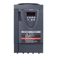
TOSVERT VFAS1-2015PL
Toshiba TOSVERT VFAS1-2015PL Manuals
Manuals and User Guides for Toshiba TOSVERT VFAS1-2015PL. We have
1
Toshiba TOSVERT VFAS1-2015PL manual available for free PDF download: Instruction Manual
Toshiba TOSVERT VFAS1-2015PL Instruction Manual (293 pages)
The new generation high-performance inverter
Brand:
Toshiba
| Category:
Inverter
| Size: 6.23 MB
Table of Contents
Table of Contents
9
1 Read First
14
Check Product Purchase
14
Contents of the Product
14
Names and Functions
15
Outside View
15
Main Circuit, Control Power Supply and Control Circuit Terminal Boards
17
Detaching the Terminal Board Front Cover (in Case of Models 200V-15Kw or Smaller, 400V-18.5Kw or Smaller
24
Notes on the Application
25
Motors
25
Inverters
27
What to Do about the Leak Current
28
Installation
30
2 Connection Equipment
35
Cautions on Wiring
35
Standard Connections
37
Description of Terminals
42
Main Circuit Terminals
42
Control Circuit Terminals (Sink Logic (Minus Common:CC
43
Serial RS485 Communication Connector
48
Operations
50
3 Operations
51
Setting/Monitor Modes
51
Simplified Operation of the VF-AS1
52
Terminal Board Operation
52
Panel Operation
56
4 Searching and Setting Parameters
58
How to Set Parameters
59
Setting Parameters in the Quick Mode
59
Setting Parameters in the Standard Setting Mode
60
Functions Useful in Searching for a Parameter or Changing a Parameter Setting
61
Basic Parameters
62
5 Basic Parameters
62
History Function
62
Setting Acceleration/Deceleration Time
63
Automatic Acceleration/Deceleration
63
Manually Setting Acceleration/Deceleration Time
64
Increasing Starting Torque
64
Setting Parameters by Operating Method
66
Selection of Operation Mode
67
Selecting Control Mode
72
Manual Torque Boost-Increasing Torque Boost at Low Speeds
76
Base Frequency
76
Maximum Frequency
77
Upper Limit and Lower Limit Frequencies
77
Setting Frequency Command Characteristics
78
Preset Speed Operation (Speeds in 15 Steps
78
Selecting Forward and Reverse Runs (Operation Panel Only
81
Setting the Electronic Thermal
82
Changing the Display Unit % to a (Ampere)/V (Volt
86
Meter Setting and Adjustment
87
PWM Carrier Frequency
91
Trip-Less Intensification
93
Auto-Restart (Restart During Coasting
93
Regenerative Power Ride-Through Control/Deceleration Stop During Power Failure/Synchronized Acceleration/Deceleration
95
Dynamic (Regenerative) Braking - for Abrupt Motor Stop
97
Standard Default Setting
103
Searching for All Reset Parameters and Changing Their Settings
104
EASY Key Function
106
6 Extended Parameters
108
Input/Output Parameters
108
Low-Speed Signal
108
Putting out Signals of Arbitrary Frequencies
109
Input Signal Selection
110
Priority When Forward/Reverse Run Commands Are Entered Simultaneously
110
Assigning Priority to the Terminal Board in the Operation Panel and Operation Mode
111
Binary/Bcd Signal Selection (Expansion TB Option Unit
112
Analog Input Signal Switching
112
Terminal Function Selection
113
Keeping an Input Terminal Function Always Active (on
113
Modifying Input Terminal Functions
113
Using the Servo Lock Function
115
Modifying Output Terminal Functions
115
Response Time of Input/Output Terminals
116
Basic Parameters
116
Switching Among V/F Characteristics 1, 2, 3 and 4 from Input Terminal
116
V/F 5-Point Setting
118
Speed/Torque Command Gain and Bias
118
Using Two Types of Frequency (Speed) Commands
118
Operation Frequency
118
Start Frequency/Stop Frequency
120
Run/Stop Control with Frequency Setting Signals
120
Frequency Setting Signal 0Hz Dead Zone Handling Function
121
DC Braking
121
DC Braking
122
Motor Shaft Fixing Control
123
Function of Issuing a 0Hz Command During a Halt
124
Auto-Stop in Case of Lower-Limit Frequency Continuous Operation
125
Jog Run Mode
126
Setting Frequency Via External Contact Input (Up/Down Frequency Setting
127
Jump Frequency - Jumping Resonant Frequencies
129
Preset Speed Operation Frequencies
130
Preset Speed Operation Frequency 8 to
130
Trip-Less Intensification
131
Retry Function
131
Avoiding Overvoltage Tripping
132
Output Voltage Adjustment/Supply Voltage Correction
132
Reverse Run Prohibition
134
Drooping Control
134
Light-Load High-Speed Operation Function
135
Braking Function
136
Acceleration/Deceleration Suspend Function
138
Commercial Power/Inverter Switching
139
PID Control
140
Stop Position Control Function
141
Setting Motor Constants
143
Motor Current Stabilization Adjustment
146
Torque Control
146
Torque Command
146
Speed Limits in Torque Control Mode
147
Torque Bias and Load Sharing Gain
147
Torque Limit
149
Torque Limit Switching
149
Torque Limit Mode Selection at Acceleration/Deceleration
151
Stall Prevention Function
153
Power Running Stall Continuous Trip Detection Time
153
Regenerative Braking Stall Prevention Mode Selection
153
Current and Speed Control Gain
153
Fine Adjustment of Frequency Setting Signal
154
Operating a Synchronous Motor
154
Acceleration/Deceleration
155
Setting Acceleration/Deceleration Patterns and Switching Acceleration/Deceleration Patterns 1, 2, 3 and
155
Pattern Operation
158
Preset Speed Mode
161
Protection Functions
161
Setting of Stall Prevention Level
161
Inverter Trip Record Retention
161
Emergency Stop
162
Output Phase Failure Detection
163
OL Reduction Starting Frequency
163
Motor 150%-Overload Time Limit
163
Input Phase Failure Detections
163
Control Mode for Low Current
164
Detection of Output Short Circuit
164
Overtorque Trip
165
Cooling Fan Control Selection
166
Cumulative Operation Time Alarm Setting
166
Abnormal Speed Detection
167
Overvoltage Limit Operation
167
Undervoltage Trip
167
Regenerative Power Ride-Through Control Level
168
Braking Answer Waiting Time
168
Analog Input Wire Breakage Detection Level
168
Guide to Time of Replacement
169
Rush Current Suppression Relay Activation Time
169
Motor Thermal Protection
169
Braking Resistance Overload Curve
169
Override
170
Adjustment Parameters
172
Pulse Train Output for Meters
172
Setting of Optional Meter Outputs
173
Calibration of Analog Outputs
173
Operation Panel Parameter
174
Prohibition of Key Operations and Parameter Settings
174
Displaying the Rotational Speed of the Motor or the Line Speed
175
Changing the Steps in Which the Value Displayed Changes
176
Changing the Standard Monitor Display
177
Canceling the Operation Command
177
Selection of Operation Panel Stop Pattern
177
Setting of a Torque Command in Panel Operation Mode
177
Torque-Related Parameters for Panel Operation
178
Tracing Functions
178
Communication Function
182
2-Wire RS485/4-Wire RS485
182
Open Network Option
188
My Function
188
Instruction Manuals for Optionally Available Devices and Special Functions
189
7 Operation with External Signal
190
External Operation
190
Applied Operation with Input and Output Signals (Operation by Terminal Board
191
Functions of Input Terminals (in Case of Sink Logic
191
Functions of Output Terminals (Incase of Sink Logic
194
Setup of Input/Output Terminal Operation Time
198
Analog Input Filter
198
Setup of External Speed Command (Analog Signal
199
Setup by Analog Input Signals (RR/S4 Terminal
200
Setup by Analog Input Signals (VI/II Terminal
201
Setup by Analog Input Signals (RX Terminal
202
8 Monitoring the Operation Status
203
Screen Composition in the Status Monitor Mode
203
Monitoring the Status
204
Status Monitor under Normal Conditions
204
Display of Detailed Information on a Past Trip
208
Changing Status Monitor Function
209
Display of Trip Information
211
Trip Code Display
211
Monitor Display at Tripping
213
Display of Alarm, Pre-Alarm, Etc
215
9 Taking Measures to Satisfy the CE/UL/CSA Standards
216
How to Cope with the CE Standard
216
EMC Directive
216
Measures to Satisfy the EMC Directive
217
Low-Voltage Directive
220
Measures to be Taken to Satisfy the Low-Voltage Directive
220
Measures to be Taken to Satisfy the UL/CSA Standards
221
Caution in Installing the Inverter
221
Caution in Wiring
221
Caution as to Peripheral Devices
221
Caution as to the Protection of Motors from Overload
223
10 Selection of Peripheral Devices
224
11 Table of Parameters
226
12 Specifications
272
Specifications
272
Models and Their Standard Specifications
272
Outside Dimensions and Mass
276
13 Before Making a Servicecall- Trip Information and Remedies
280
Trip Causes/Warnings and Remedies
280
Method of Resetting Causes of Trip
285
If the Motor Does Not Run While no Trip Message Is Displayed
286
How to Check Other Troubles
287
14 Inspection and Maintenance
288
Regular Inspection
288
Periodical Inspection
289
Making a Call for Servicing
291
Keeping the Inverter in Storage
291
Warranty
292
15 Warranty
293
16 Disposal of the Inverter
293
Advertisement
Advertisement
Related Products
Toshiba TOSVERT VFAS1-2004PL
Toshiba TOSVERT VFAS1-2022PL
Toshiba TOSVERT VFAS1-2037PL
Toshiba TOSVERT VFAS1-2055PL
Toshiba TOSVERT VFAS1-2075PL
Toshiba TOSVERT VFAS1-2185PM
Toshiba TOSVERT VFAS1-2230PM
Toshiba TOSVERT VFAS1-2300PM
Toshiba TOSVERT VFAS1-2450PM
Toshiba TOSVERT VFAS1-2550P
Toshiba Categories
Laptop
Air Conditioner
TV
LCD TV
All in One Printer
More Toshiba Manuals
Login
Sign In
OR
Sign in with Facebook
Sign in with Google
Upload manual
Upload from disk
Upload from URL