Sign In
Upload
Manuals
Brands
YASKAWA Manuals
Servo Drives
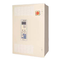
E7LVA002
YASKAWA E7LVA002 Manuals
Manuals and User Guides for YASKAWA E7LVA002. We have
1
YASKAWA E7LVA002 manual available for free PDF download: Technical Manual
YASKAWA E7LVA002 Technical Manual (306 pages)
Drive/Bypass
Brand:
YASKAWA
| Category:
Servo Drives
| Size: 4.26 MB
Table of Contents
Notes
9
Warnings and Cautions
3
Introduction
5
Table of Contents
9
Chapter 1 - Physical Installation
14
Bypass Model Number and Enclosure Style
14
Enclosure Data
15
Bypass Unit Enclosures
17
Confirmations Upon Delivery
18
Nameplate Information
18
Receiving Checks
18
Bypass Product Options
20
Bypass Component Descriptions
22
Bypass Unit Front Control Panel
22
Internal Bypass Panel
24
Exterior and Mounting Dimensions
28
Bypass Unit 30 HP and Below, 480 VAC; 15 HP and Below, 208V/240V
28
Bypass Unit 40 HP to 60 HP, 480 VAC; 20 HP to 30 HP, 208V/240V
29
Dimensions and Weights
30
Checking and Controlling Installation Site
31
Installation Site
31
Controlling the Ambient Temperature
32
Installation Orientation and Enclosure Considerations
32
Protecting the Bypass Unit from Foreign Matter
32
Chapter 2 Electrical Installation
33
Termination Configuration - Power Wiring
34
Field Wiring, Pressure Wire Connector, Wire Type, Range and Tightnening Torque Specifications
35
Cable Length between Drive and Motor
36
Grounding
37
Wire Routing
38
E7 Drive Main Circuit Configurations 208-240 VAC
39
E7 Drive Main Circuit Configurations 480 VAC
39
Control Wiring
40
Bypass Field Control Wire Landing
40
Annunciation Contacts
41
Building Automation System Interlock Circuit (Drive and Bypass Enable Input)
42
Building Automation System Run/Stop Circuit
42
Safety Interlock Circuit
42
Analog Inputs
43
Analog Outputs
45
Serial Communications
46
Multi-Function Digital Inputs
48
Remote Transfer to Bypass
48
Smoke Purge Operation
48
DIP Switch Programmable Functions Summary
49
Bypass Controller PCB
50
Control Circuit Wiring Precautions
51
Wiring Checks
51
Bypass Control Circuit Terminal Functions
52
Wiring Diagram
54
Electrical Overview
56
Chapter 3 Control Panel
57
Digital Operator and Control Panel Display
58
Digital Operator and H/O/A Control Panel Keys
59
Drive Digital Operator/Keypad
60
Control Panel Indicator Lights (Leds)
62
Selector Key Indicators
65
Normal Control Panel Indicators
65
Abnormal Control Panel Indicators
66
Fault Control Panel Indicators
66
Drive Main Menus
67
Main Menu Structure
68
DRIVE - Operation Menu
69
QUICK - Quick Setting Menu
72
ADV- Programming Menu
74
VERIFY - Modified Constants (Parameters) Menu
76
A.TUNE - Auto-Tuning Menu
77
Example of Changing a Parameter
78
Chapter 4 Start up and Operation
79
Start up Introduction
80
The Safety Interlock Circuit at Power up
80
The BAS Interlock Circuit at Power up
81
Bypass Unit Start up Preparation
82
Bypass Unit Start up Procedure
83
Bypass Unit Operation Description
88
Selector Key Functions
90
DIP Switch Selectable Functions
90
Contact Closure Inputs
92
Chapter 5 Programming
93
Regarding Chapter 5
94
Standard LED Keypad Display and Optional LCD Keypad Display
94
Programming for Various Configuration and Options
94
Programming Instructions for Individual Drive Parameters
94
Virtual Terminals
94
Bypass Unit Basic Programming Parameters
96
Discussion of Table 5.2 Option-Dependent Bypass Parameter Settings
99
Drive Parameters
102
A1 Initialization
102
B1 Sequence
104
B2 DC Braking
109
B3 Speed Search
111
B5 PI Function
115
B8 Energy Savings
129
C1 Accel/Decel
130
D1 Preset References
131
D2 Reference (Speed Command) Limits
133
D4 Sequence
135
E1 V/F Pattern
136
E2 Motor Setup
139
F6 Com OPT Setup
140
H1 Digital Inputs
141
H3 Analog Inputs
146
L2 Momentary Power Loss Ride-Thru Function
152
L3 Stall Prevention
153
L4 Speed Command Loss Detection
156
L5 Fault Restart
157
L6 Torque Detection
159
L8 Hardware Protection
161
O1 Monitor Configuration
163
O2 Key Selections
167
O3 Digital Operator Copy Function
170
T1 Auto-Tuning
172
Chapter 6 Diagnostics & Troubleshooting
173
E7L Bypass PCB and H/O/A Control Panel Diagnostics
174
Introduction
174
Set up for Maintenance Mode
174
Specifications
174
Testing
175
Drive Diagnostics
178
Fault Detection
179
Alarm Detection
185
Operator Programming Errors (OPE)
188
Auto-Tuning Faults
189
Digital Operator COPY Function Faults
190
Drive Troubleshooting
191
If Parameter Cannot be Set
191
If the Motor Does Not Operate
192
If the Motor Does Not Put out Torque or if Acceleration Is Slow
193
If the Motor Operates at a Higher Speed than the Speed Command
193
The Direction of the Motor Rotation Is Reversed
193
If Peripheral Devices Like Plcs or Others Are Influenced by Starting or Running Drive
194
If the Motor Overheats
194
If a Stand Alone Ground Fault Interrupter Operates When the Drive Is Run
195
If There Is Mechanical Vibration
195
If the Motor Rotates Even When Drive Output Is Stopped
196
If Zero Volts Is Detected When a Motor Is Started, or Stalls
196
Drive Main Circuit Test Procedure
197
Drive Date Stamp Information
201
Chapter 7 Maintenance
203
E7L Maintenance
204
Periodic Inspection
204
Preventive Maintenance
205
Replacing the Controller PCB A2
206
Replacing the H/O/A Control Panel
206
Drive Heatsink Cooling Fan Replacement
207
Removing and Replacing the Drive in a Bypass Unit
209
Drive Replacement
209
Appendix A Parameters
213
Chapter 7 - Maintenance
213
Parameter List
214
This Appendix Lists All the Parameter Numbers and Names, Along with a Description
214
Monitor List
238
Fault Trace List
240
Fault History List
241
Decimal to Hex Conversion
242
Appendix B - Capacity Related Parameters
243
Drive Capacity
244
Appendix C Specifications
249
Standard Drive and Bypass Specifications
250
Appendix D Communication
253
E7L and Serial Communication
254
This Appendix Details the Specifications, Connections, and Programming of the Drive
254
Using Modbus Communication
255
Communication Specifications
255
Modbus Communication Configuration
255
Communication Connection Terminal
256
Procedure for Setting up Communication
256
Modbus Function Code Details
260
Modbus Self-Diagnosis
267
Metasys N2 Point Database
268
Metasys N2 Analog Input (AI) Summary
268
Metasys N2 Binary Input (BI) Summary
270
Metasys N2 Binary Output (BO) Summary
270
Mailbox Function Points
271
APOGEE FLN Point Database
272
APOGEE FLN Point List Summary
272
Mailbox Function Points
278
Appendix E Peripheral Devices
281
Branch Circuit Short Circuit Protection
282
Branch Circuit Overload Protection
285
Peripheral Devices
286
Appendix F Replacement Parts
287
Primary Drive Replacement Parts - 208/230/240VAC
288
Primary Drive Replacement Parts - 480VAC
289
Bypass Replacement Parts
290
Index
304
Advertisement
Advertisement
Related Products
YASKAWA E7LVA003
YASKAWA E7LVA004
YASKAWA E7LVA006
YASKAWA E7LVA009
YASKAWA E7LVA022
YASKAWA E7LVA028
YASKAWA E7LVA054
YASKAWA E7LVA080
YASKAWA E7LVA068
YASKAWA E7LVA042
YASKAWA Categories
Controller
DC Drives
Servo Drives
Robotics
Inverter
More YASKAWA Manuals
Login
Sign In
OR
Sign in with Facebook
Sign in with Google
Upload manual
Upload from disk
Upload from URL