Sign In
Upload
Manuals
Brands
York Manuals
Controller
OPTIVIEW YK
York OPTIVIEW YK Manuals
Manuals and User Guides for York OPTIVIEW YK. We have
1
York OPTIVIEW YK manual available for free PDF download: Service Instructions Manual
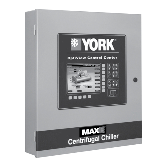
York OPTIVIEW YK Service Instructions Manual (390 pages)
CONTROL CENTER
Brand:
York
| Category:
Controller
| Size: 9.15 MB
Table of Contents
TABLE 1 - Control Panel Applications
4
Table of Contents
5
Section 1 - Introduction
15
Section 2 - System Architecture
17
FIGURE 1 - Optiview Control Center - Electromechanical Starter Applications
22
FIGURE 2 - Optiview Control Center - MOD a Solid State Starter Applications
23
FIGURE 3 - Optiview Control Center - MOD B Solid State Starter Applications
24
FIGURE 4 - Optiview Control Center - Medium Voltage Solid State Starter Applications
25
FIGURE 5 - Optiview Control Center - Compressor Motor Variable Speed Drive (YORK Serial Communications Protocol)
26
FIGURE 6 - Optiview Control Center - Compressor Motor Variable Speed Drive
27
(Modbus Serial Communications Protocol)
27
FIGURE 7 - Optiview Control Center - Compressor Motor Medium Voltage Variable Speed Drive
28
FIGURE 8 - Operation Sequence Timing Diagram (Electromechanical and Solid State Starter Applications)
29
FIGURE 9 - Operation Sequence Timing Diagram (Compressor Motor Variable Speed Drive Applications)
30
Section 3 - Microboard 031-01730-000
31
Boot-Up Step and Description
33
TABLE 2 - Boot-Up LED Indicators
33
TABLE 3 - Addresses and Associated Data
34
Power Supply
38
Service Replacement
38
FIGURE 11 - Flash Memory Card
40
FIGURE 12 - Microboard (031-01730-000) Power Supply Test Points
41
Program Jumpers
42
Program Switches
44
FIGURE 13 - Microboard Lamp Dimmer Circuit
45
FIGURE 14 - Microboard Serial Data Communications Ports
46
FIGURE 15 - Configurable Analog and Remote Setpoint Inputs
47
Section 4 - Microboard 031-02430-000 and 031-02430-001
49
Description
49
TABLE 4 - Diagnostic Display Codes
50
TABLE 5 - Multiplexer Channels
53
Configuration and Setup
58
FIGURE 16 - BRAM Socket
62
TABLE 6 - Summary of Differences
62
TABLE 7 - Microboard
62
Downloading a Program from Aprogram Card
63
Program Jumpers
64
Program Switches
65
FIGURE 17 - Microboard 031-02430-000 and 031-02430-001
66
FIGURE 18 - Program Card 031-02474-001
67
FIGURE 19 - Microboard (031-02430-000 and 031-02430-001) DC Power Supply Test Points
67
FIGURE 20 - Microboard Lamp Dimmer Circuit
68
FIGURE 21 - Microboard Serial Data Communications Ports
69
FIGURE 22 - Configurable Analog and Remote Setpoint Inputs
70
FIGURE 23 - Configurable Analog and Remote Setpoint Inputs (Heat Pump Duty)
71
FIGURE 24 - Low Voltage Digital Inputs
72
Section 5 - Microboard 031-03630-001
73
Chiller Operating Program
74
TABLE 8 - Diagnostic Display Codes
74
Program Jumpers
77
Program Switches
78
TABLE 9 - Multiplexer Channels
79
Configuration and Setup
84
Downloading a Program from Aprogram Card
88
FIGURE 25 - Microboard 031-03630-001
90
FIGURE 26 - Program Card 031-03601-001
91
FIGURE 27 - Microboard (031-03630-001) DC Power Supply Test Points
91
FIGURE 28 - Microboard Lamp Dimmer Circuit
92
FIGURE 29 - Microboard Serial Data Communication Ports
93
FIGURE 30 - Configurable Analog and Remote Setpoint Inputs
94
FIGURE 31 - Configurable Analog and Remote Setpoint Inputs (Heat Pump Duty)
95
FIGURE 32 - Low Voltage Digital Inputs
96
Section 6 - I/O Board
97
I/O Board
97
Digital Inputs
97
Digital Outputs
97
Triacs
98
Relay Timing
98
FIGURE 33 - I/O Board
101
FIGURE 34 - I/O Board Digital Inputs
102
FIGURE 35 - I/O Board Typical Optocoupler Circuit
103
FIGURE 36 - I/O Board Typical Field Connections
103
FIGURE 37 - J1 I/O Board Digital Outputs
104
Section 7 - Liquid Crystal Display
107
Backlight Lamp Replacement
109
FIGURE 38 - Display Mounting
110
FIGURE 39 - Liquid Crystal Display Assembly - Sharp LQ10D367/368 (031-01774-000) Display
111
FIGURE 40 - Liquid Crystal Display Assembly - Sharp LQ104V1DG61 (031-02886-000) Display
111
FIGURE 41 - Liquid Crystal Display Assembly - LG Semicon LP104V2-W (031-02046-000)
112
FIGURE 42 - Liquid Crystal Display Assembly - Sharp LQ104V1DG81 (031-01771-000)
112
FIGURE 43 - Liquid Crystal Display Typical Control Signal Timing
113
FIGURE 44 - Display (Sharp LQ10D367/368) Lamp Replacement
113
FIGURE 45 - Display (Sharp LQ104V1DG61 (031-02886-000) and LG LP104V2-W (031-02046-000))
114
Section 8 - Display Interface Board
115
FIGURE 46 - Display Interface Board 031-01765-001 and 031-01765-002
117
FIGURE 47 - Display Interface Board 031-02887-000
118
Section 9 - Display Backlight Inverter Board
119
FIGURE 48 - Display Backlight Inverter Board (Sharp LQ10D367/368 (031-01774-000) and LG Semicon LP104V2-W (031-02046-000))
120
FIGURE 49 - Display Backlight Inverter Board - Sharp LQ104V1DG61 Display 031-02886-000
121
Section 10 - Keypad
123
FIGURE 50 - Keypad Interface
124
FIGURE 51 - Keypad
125
Section 11 - Power Supply
127
FIGURE 52 - Power Supply
127
FIGURE 53 - Power Supply - DC Power Distribution (Refer to Optiview Control Center Wiring Diagram for Wire Connections)
128
Section 12 - Current Module (CM-2)
129
TABLE 10 - MUX Address
130
FIGURE 54 - CM-2 Current Module (Electromechanical Starter Application)
131
FIGURE 55 - CM-2 Current Module (Electromechanical Starter Applications)
131
FIGURE 56 - CM-2 Current Module - Interface, Current Transformers, and Variable Resistors
132
Section 13 - Solid State Starters
133
Solid State Starters
133
Medium Voltage Solid State Starter
133
FIGURE 57 - Style B Liquid Cooled Solid State Starter (LCSSS) - Interface (YORK Protocol)
137
FIGURE 58 - Style B Liquid Cooled Solid State Starter (LCSSS) - Interface (YORK Protocol)
137
FIGURE 59 - Style B Liquid Cooled Solid State Starter (LCSSS) - Interface (Modbus Protocol)
138
FIGURE 60 - Solid State Starter Logic Board
138
TABLE 11 - Microboard Multiplex Channels
140
FIGURE 61 - Mod a Liquid Cooled Solid State Starter (LCSSS) - Interface
141
Section 14 - Adaptive Capacity Control Board
143
YORK Protocol Configuration
143
Modbus Protocol Configuration
150
FIGURE 62 - Compressor Motor Variable Speed Drive (VSD) Adaptive Capacity Control (ACC) Board
152
FIGURE 63 - Serial Communications Interface - YORK Protocol
153
FIGURE 64 - Serial Communications Interface - Modbus Protocol
154
FIGURE 65 - Adaptive Capacity Control (ACC) Board
155
Section 15 - Proximity Probe
157
TABLE 12 - Proximity Probes
159
FIGURE 66 - Proximity Probe Interface - Probe Part Number 025-30961-000
160
FIGURE 67 - Proximity Probe Interface - Probe Part Number 025-35900-000 and 025-35900-001
160
FIGURE 68 - Proximity Probe Interface - Probe Part Number 025-40496-000
161
FIGURE 69 - Proximity Probe
162
Section 16 - High Speed Thrust Bearing Limit Switch
163
FIGURE 70 - High Speed Thrust Bearing Limit Switch - Interface
163
FIGURE 71 - High Speed Thrust Bearing Limit Switch
164
Section 17 - Refrigerant Level Control
165
Automatic Operation
165
Manual Operation
167
Actuators
167
FIGURE 72 - Refrigerant Liquid Level Sensor
168
FIGURE 73 - Refrigerant Liquid Level Control - Interface
169
Section 18 - Oil Pump Variable Speed Drive
171
Automatic Operation
171
Manual Operation
172
Oil Heater Operation
173
FIGURE 74 - Oil Pump Variable Speed Drive (VSD)
173
FIGURE 75 - Oil Pump VSD / Oil Heater Control - Interface
174
FIGURE 76 - Oil Pump VSD Speed Control Signal
174
Section 19 - Communications
175
FIGURE 77 - E-Link Gateway Interface Block Diagram
175
Section 20 - Pressure Transducers
177
FIGURE 78 - Pressure Transducers
178
TABLE 13 - Pressure Transducer Applications
179
Section 21 - Temperature Thermistors
181
TABLE 14 - Leaving Chilled Liquid Temperature
182
TABLE 16 - Return Chilled Liquid Temperature
188
TABLE 18 - Return and Leaving Condensing Water
192
TABLE 19 - Oil and Discharge Temperature
195
TABLE 20 - Drop Leg Refrigerant Sensor
200
TABLE 21 - Evaporator Refrigerant Sensor
200
TABLE 22 - Leaving and Return Heating Condenser Water Temperature Sensor
201
Section 22 - Remote Setpoints
203
Remote Operating Modes
203
Current Limit
203
Leaving Chilled Liquid Temperature
205
Leaving Condenser Liquid Temperature (Heat Pump Mode)
207
Section 23 - Hot Gas Bypass
211
Setpoints
211
Operation
212
Hot Gas Operation with Variable Geometry Diffuser (VGD)
213
Manual Control
213
I/O Board
213
Pre-Rotation Vanes Potentiometer
214
FIGURE 79 - Interface, Hot Gas Bypass (Analog I/O Board 371-02514-000)
215
FIGURE 80 - Interface, Hot Gas Bypass (I/O Board 031-02895-000)
216
Section 24 - Smart Freeze Protection
217
Section 25 - Surge Protection
219
Surge Detection
219
Excess Surge Detection
220
Surge Protection
220
Hot Gas Bypass/Compressor Motor Variable Speed Drive (VSD) Applications
221
Section 26 - Variable Geometry Diffuser
223
Stall Detection
223
Surge Detection
223
Automatic Operation
223
Stall Sensor Validation
225
Extreme Stall Monitor
225
Manual Operation
226
Setpoints
226
Pre-Rotation Vanes Position
227
I/O Board
227
Stall Transducer
227
Stall Detector Board
227
FIGURE 81 - Variable Geometry Diffuser Block Diagram
228
FIGURE 82 - Variable Geometry Diffuser State Diagram
229
Section 27 - Large Tonnage Chiller (Ltc) I/O Board 031-02895-000/001
231
Digital Inputs
231
FIGURE 83 - LTC I/O Board Basic Block Diagram
232
FIGURE 84 - 120 VAC Digital Input
232
Digital Outputs
233
FIGURE 85 - +5 VDC Digital Input
233
FIGURE 86 - Relay Outputs
233
FIGURE 87 - Triac Outputs
233
Analog Inputs
234
FIGURE 88 - Open Collector
234
FIGURE 89 - Analog Inputs
234
Analog Outputs
235
FIGURE 90 - Analog Outputs
235
Auto Detection
236
Diagnostic Screen
236
FIGURE 91 - I/O Board (031-02895-XXX)
236
Section 28 - Heat Recovery
237
Inputs/Outputs
237
Control
237
FIGURE 92 - Heat Recovery Block Diagram
238
FIGURE 93 - PID Controller Diagram
239
FIGURE 94 - Heat Recovery Flow Diagram
240
Remote Hot Water Setpoint
241
Condenser Flow Switch Open Fault
241
TABLE 23 - Control Source Setpoints
241
Section 29 - Head Pressure Control
243
Inputs/Outputs
243
FIGURE 95 - Head Pressure Control Block Diagram
243
Control
244
FIGURE 96 - Head Pressure Control Flow Diagram
244
Operation When Equipped with both Heat Recovery and Head Pressure Control
245
Section 30 - Quick Start
247
Quick Start Modes
247
Setpoints
247
Operation
249
TABLE 24 - Compare a Normal Start, Quick Normal Start, and a Quick Restart
250
Section 31 - Heat Pump Duty
253
Inputs/Outputs
253
Setpoints
253
Control
254
Hot Gas Bypass Control
255
Heat Recovery and Head Pressure Control
255
Quick Start
255
Variable Speed Drive
255
Condenser Temperature Range
255
Condenser High Pressure Warning
255
GPIC Objects
255
FIGURE 97 - Heat Pump Duty Block Diagram
256
Section 32 - Motor Monitoring
257
FIGURE 98 - Motor Monitoring Board (031-02893-000/001)
257
FIGURE 99 - Motor Monitoring Board Basic Block Diagram
258
Motor Monitoring Board
259
FIGURE 100 - Motor Monitoring Block Diagram
260
Winding Temperatures
262
FIGURE 101 - Winding Temperature - Thermistors
262
Bearing Temperatures
264
FIGURE 102 - Winding and Bearing Temperature - RTD
264
Vibration
265
FIGURE 103 - Bearing Vibration Sensor
265
Cooling Coil Leak Detection
267
FIGURE 104 - Motor Cooling Coil Leak Detector - Float Sensor
267
FIGURE 105 - Motor Cooling Coil Leak Detector - Optical Sensor
268
TABLE 25 - RTD Resistance/Temperature Chart
269
TABLE 26 - Thermistor Resistance/Temperature Chart
269
Section 33 - System Calibration, Service Setpoints, and Reset Procedures
271
Electromechanical Starter Applications
271
Solid State Starter Applications
272
Compressor Motor Variable Speed Drive Applications
276
Proximity Probe
279
High Speed Thrust Bearing Limit Switch
280
Refrigerant Level Control
280
Oil Pump Variable Speed Drive
282
Oil Return Min
283
Standby Lubrication
283
High Condenser Pressure Warning Threshold
283
Brine Low Evaporator Pressure Cutout
284
Leaving Chilled Liquid Temperature Control Sensitivity
284
Drop Leg Refrigerant Temperature
284
Smart Freeze Protection
285
Evaporator Refrigerant Temperature
285
Hot Gas Bypass Control
285
Chiller Starts and Operating Hours Reset
286
Service Phone Numbers
286
Surge Protection
287
Sales Order Data
287
Custom User ID and Passwords
288
Record Setpoint Changes
289
Chiller Style/Compressor
289
TABLE 27 - Flash Memory Card Version C.MLM.01.07.XXX and C.MLM.01.07A.XXX
290
TABLE 28 - Flash Memory Card Version C.MLM.01.08.XXX
291
TABLE 29 - Flash Memory Card Version C.MLM.01.08.105A and C.MLM.01.08.206A (and Later)
291
TABLE 30 - Software Version C.MLM.01.10B.XXX (and Later) or C.OPT.01.10B.XXX (and Later)
291
Flow Switch
292
TABLE 31 - Software Version C.OPT.01.16.XXX (and Later)
292
Microboard 031-02430-000-001 and 031-03630-001 Setup/Configuration
293
Variable Geometry Diffuser
293
High Condenser Pressure Fault While Shutdown - Reset Procedure
295
Motor Lubrication Notification
295
Quick Start
298
Heat Pump Duty
299
Motor Monitoring Software (Version C.opt.01.22.307 and Later)
299
Motor Details Screen
299
Motor Setpoints Screen
301
Section 34 - Diagnostics and Troubleshooting
305
Diagnostics Screen
306
FIGURE 106 - Diagnostics Screen
306
Serial/Sd Screen
307
FIGURE 107 - Serial/Sd Screen
307
Main Diagnostics Screen
308
FIGURE 108 - Main Diagnostics
308
Motor Monitoring Board Diagnostic Screen
309
FIGURE 109 - Motor Monitoring Board Diagnostic Screen
309
I/O Board (031-02895-000) Diagnostic Screen
311
FIGURE 110 - I/O Board Diagnostic Screen
311
Keypad Test
313
FIGURE 111 - Keypad Test Screen
313
Display Test Main Screen
314
FIGURE 112 - Display Test Main Screen
314
Bit Patterns Test Screen
316
FIGURE 113 - Bit Patterns Test Screen
316
Serial Inputs/Outputs Test Screen
318
FIGURE 114 - Serial Inputs/Outputs Test Screen
318
FIGURE 115 - Microboard - COM 5 Serial Data Port
319
Digital Inputs/Outputs Test Screen
320
FIGURE 116 - Digital Inputs/Outputs Test Screen
320
Analog Inputs Test Screen
323
FIGURE 117 - Analog Inputs Test Screen
323
Section 35 - System Commissioning Checklist
327
Section 36 - Software Enhancements
333
SI0006 - Software Enhancements Effective May 2001
333
SI0019 - Software Enhancements Effective March 2002
335
SI0034 - Software Enhancements Effective August 2002
337
SI0058 - Software Enhancements Effective February 2003
340
SI0062 - Software Enhancements Effective March 2003
342
SI0080 - Software Enhancements Effective January 2004
343
SI0089 - Software Enhancements Effective May 2004
345
SI0148 - Software Enhancements Effective June 2006
349
SI0158 - Software Enhancements Effective October 2006
350
SI0164 - Software Enhancements Effective April 2007
351
SI0186 - Software Enhancements Effective October 2006
354
SI0201 - Software Enhancements (Ver 19) Effective October 2008
356
SI0210 - Software Enhancements (Ver 20) Effective June 2009
361
SI0212 - Software Enhancements (Ver 21) Effective June 2009
363
SI0224 - Software Enhancements (Ver 22) Effective April 2010
368
SI0252 - Software Enhancements (Ver 23) Effective May 2011
369
TABLE 32 - Loop Back Connections
371
SI0265 - Software Enhancements (Ver 24) Effective May 2012
372
SI0271 - Software Enhancements (Ver 25) Effective August 2013
374
FIGURE 118 - Diagnostic Screen
377
TABLE 33 - Data Logging
378
FIGURE 119 - Head Pressure Control Screen
381
FIGURE 120 - Power Fault Recovery Screen
382
Si0300 - Software Enhancements (Ver 27) Effective June 2015
384
TABLE 34 - si Metric Conversion
389
Advertisement
Advertisement
Related Products
York OPTIVIEW
York OPTIVIEW YIA D
York OPTIVIEW YD Series
York CCWEB01
York CIW01
York DWCPXY
York ECHC 09 DSAAAR
York ECHC 12 DSAAAR
York ECHC 18 DSAAAR
York EZ Zone
York Categories
Air Conditioner
Heat Pump
Chiller
Furnace
Air Handlers
More York Manuals
Login
Sign In
OR
Sign in with Facebook
Sign in with Google
Upload manual
Upload from disk
Upload from URL