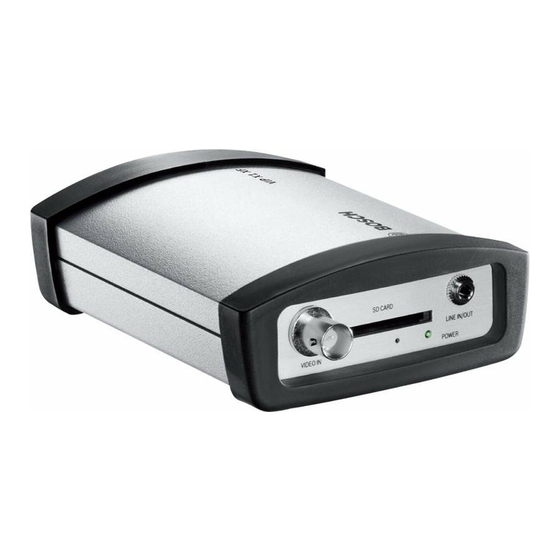
Bosch VIP X1 XF Quick Installation Manual
Hide thumbs
Also See for VIP X1 XF:
- Installation and operating manual (132 pages) ,
- Quick installation manual (19 pages) ,
- Installation manual (2 pages)
Table of Contents
Advertisement
Quick Links
Advertisement
Table of Contents

Summary of Contents for Bosch VIP X1 XF
- Page 1 VIP X1 XF Network Video Server Quick Installation Guide...
- Page 3 Operating Manual (see product CD). This contains important information on installation and operation. Only operate the VIP X1 XF in combination with an LPS/NEC Class 2 power supply unit with limited output. This Quick Installation Guide only describes the basic procedure for installing a VIP X1 XF and cannot replace the complete manual.
-
Page 4: Scope Of Delivery
| Scope of Delivery VIP X1 XF Scope of Delivery – 1 VIP X1 XF network video server – 2 terminal blocks – 4 self-adhesive elastic bumpers – 1 wall-mounting panel – 2 screws – 2 wall plugs –... - Page 5 Unpacking – Check that the delivery is complete and in perfect condition. – Arrange for the unit to be checked by Bosch Security Systems if you find any damage. Bosch Sicherheitssysteme GmbH Quick Installation Guide F.01U.155.695 | V4.1 | 2009.12...
-
Page 6: Preparing For Wall-Mounting
| Preparing for Wall-Mounting VIP X1 XF Preparing for Wall-Mounting You can secure the VIP X1 XF to any load-bearing wall using the wall-mounting panel, in either a vertical or a horizontal position. CAUTION! If mounting the unit in a vertical position, you will need to use the lower plastic frame and then place the unit onto the frame from above. -
Page 7: Mounting The Frame
VIP X1 XF Mounting the Frame | en Mounting the Frame CAUTION! The mounting location must be able to reliably hold the unit. The load-bearing capacity must be adequate for four times the weight of the unit. – Lift the plastic frame on one side of the housing and carefully remove it from the unit. -
Page 8: Placing The Unit In The Frame
| Placing the Unit in the Frame VIP X1 XF Placing the Unit in the Frame – Place the unit on the wall-mounting panel, with the panel positioned between the housing and the second plastic frame. – Slide the unit into the plastic frame until you feel it lock securely into place. -
Page 9: Connecting The Camera And Audio
VIP X1 XF Connecting the Camera and Audio | en Connecting the Camera and Audio CAUTION! Please observe the following specifications: Line In: 9 kOhm typ., 5.5 Vp-p max. Line Out: 16 Ohm min., 3 Vp-p max. – Connect the camera to the socket VIDEO IN. -
Page 10: Creating A Serial Connection
Please observe the labeling on the orange socket of the VIP X1 XF and the correct position for the terminal block. – If you require a serial connection to the VIP X1 XF, connect the relevant cables to the terminal block. –... -
Page 11: Alarm And Relay Connections
Alarm and Relay Connections | en Alarm and Relay Connections CAUTION! Please observe the labeling on the orange socket of the VIP X1 XF and the correct position for the terminal block. Please observe the following specifications: Alarm Out: max. 30 V, 200 mA –... -
Page 12: Establishing The Network Connection
| Establishing the Network Connection VIP X1 XF Establishing the Network Connection – Connect the VIP X1 XF to the network via the ETH socket. F.01U.155.695 | V4.1 | 2009.12 Quick Installation Guide Bosch Sicherheitssysteme GmbH... -
Page 13: Connecting The Power Supply
Connecting the Power Supply | en Connecting the Power Supply CAUTION! Only operate the VIP X1 XF in combination with an LPS/NEC Class 2 power supply unit that has limited output and meets the following specifications: 9 to 30 V output voltage, min. -
Page 14: Assigning An Ip Address
– Start Configuration Manager. The system automatically searches the network for compatible units. – If the VIP X1 XF is displayed in the list, right-click the entry, then select Device Network Settings... from the popup menu that appears. – In the Device IP address field, enter the required IP address (for example 192.168.0.100) and click OK. - Page 16 Bosch Sicherheitssysteme GmbH Robert-Koch-Straße 100 D-85521 Ottobrunn Germany www.boschsecurity.com © Bosch Sicherheitssysteme GmbH, 2009...


