Table of Contents

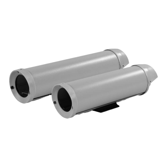
Summary of Contents for Sanyo VSE-2300 Series
- Page 1 INSTRUCTION MANUAL Cylindrical Environmental Camera Housings About this manual Before installing and using this unit, please read this manual carefully. Be sure to keep it available for later reference. VSE-2300 & VSE-2400 SERIES...
-
Page 2: Important Safeguards
IMPORTANT SAFEGUARDS 1. Read Instructions - All the safety and operating instructions should be read before the unit is operated. 2. Retain Instructions - The safety and operating instructions should be retained for future reference. 3. Heed Warnings - All warnings on the unit and in the operating instructions should be adhered to. -
Page 3: Safety Precautions
SAFETY PRECAUTIONS CAUTION: TO REDUCE THE RISK OF ELECTRICAL SHOCK, DO NOT OPEN COVERS. NO USER SERVICEABLE PARTS INSIDE. REFER SERVICING TO QUALIFIED SERVICE PERSONNEL. This label may appear on the bottom of the unit due to space limitations. The lightning flash with an arrowhead symbol within an equilateral triangle is intended to alert the user to the presence of uninsulated "dangerous voltage"... -
Page 4: Table Of Contents
Unpack carefully. This is mechanical equipment and should be handled with care. Check for the following: Housing (with correct model number). • Hardware Kit - VSE-2300 Series Models: • 1 1/4-20 x 3/8-in Button Head Screw. 2 1/4-20 x 1/2-in Button Head Screw. 2 1/4-in Spring Washers. -
Page 5: Accessories
~5 lbs. (2.3 kg) MOUNTS: ~5 lbs. (2.3 kg) MTS-2000 Mount Wall Mount: Feed-through mount attached to the foot of housing for VSE-2300 & VSE-2400 Series housings. MTS-2030 J-mount: Feed-through J-mount for VSE-2300 & VSE-2400 Series housings allows housing to be mounted from ceiling. -
Page 6: Installation
6 INSTALLATION This installation should be made by qualified service personnel and conform to the National Electrical Code and applicable local codes. TOOLS REQUIRED - Small flat blade screwdriver. - Phillips screwdriver (P2). - Adjustable wrench. - Wire cutter/stripper/crimper tool. - 5/32-in (or 4 mm) hex wrench. -
Page 7: Camera/Lens Installation
2. Remove the camera bracket from the base. If you are using the feed-through feature, refer to Section 6.8.3 at this time. Mounting fixed lens cameras in VSE-2300 and VSE-2400 Series Housings. 1. Attach the lens to the camera. 2. Use the 1/4-20 x 3/8-inch screw to mount the camera to the camera bracket. - Page 8 Remove These Dome Plugs Figure 7: Feed-through Wiring 2. Screw the two 3/8-inch NPT fittings into the foot of the housing. 3. Pull the cabling through the fittings and into the housing. Tighten the fitting to 4.0 N m to 4.5 N 40 in lb).
-
Page 9: Video Coax Connection
"INSTALLATION, Cable Requirements" for wiring of the video coax connection. 1. For VSE-2300 versions, install a 1/2-inch NPT fitting into the remaining hole in the rear cap. For VSE-2400 versions, install a 3/8-inch NPT fitting through the center small hole of the rear cap. -
Page 10: Fuse Replacement
Seal Figure 10: Reinstalling the Cover 3. As the cover nears the rear cap, make sure the captive screws in the back are not blocking the cover from engaging into the rear cap. 4. Screw the two rear captive screws into the housing. 6.11 Fuse Replacement 1. - Page 11 HOUSINGS OR INTEGRATED CAMERA/LENS/HOUSING PACKAGES In order to obtain warranty service, the product must be delivered to and picked up from an Authorized Sanyo Service Center at the user’s expense, unless specifically stated otherwise in this warranty. The names and addresses of Authorized Sanyo Service Centers may be obtained by calling the toll- free number listed below.
- Page 12 Sanyo Fisher Company Security Video Division 21605 Plummer Street Chatsworth, CA 91311 Tel: (818) 998-7322 Fax: (818) 717-2716 Technical Support: (888) 66SANYO 100 0004 001 SAN 6/02 Printed in USA...


