Table of Contents
Advertisement
Quick Links
Advertisement
Table of Contents

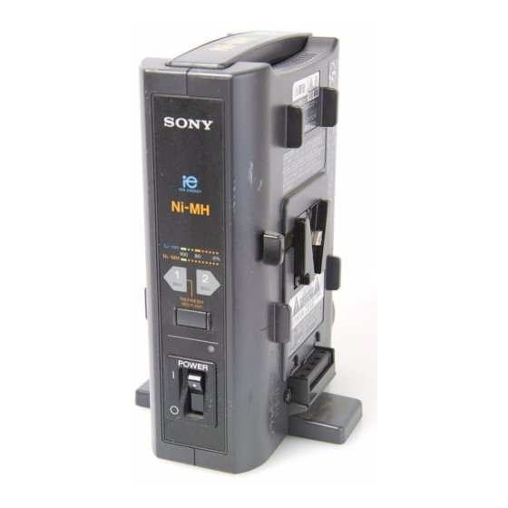
Summary of Contents for Sony BC-M50
- Page 1 BATTERY CHARGER BC-M50 SERVICE MANUAL 1st Edition...
- Page 2 Ce manual est destiné uniquement aux personnes compétentes en charge de l’entretien. Afin de réduire les risques de décharge électrique, d’incendie ou de blessure n’effectuer que les réparations indiquées dans le mode d’emploi à moins d’être qualifié pour en effectuer d’autres. Pour toute réparation faire appel à une personne compétente uniquement. BC-M50...
-
Page 3: Table Of Contents
Removing the Case L ................2-2 (E) 2-4. Removing the Boards ................2-3 (E) 3. Spare Parts 3-1. Notes on Repair Parts .................. 3-1 3-2. Exploded View .................... 3-2 3-3. Supplied Accessory ..................3-4 4. Frame Wiring Frame Wiring ....................4-2 1 (E) BC-M50... -
Page 5: Manual Structure
Manual Structure Purpose of this manual This is the Service Manual of the Battery Charger BC-M50. This manual is intended for use by service engineers and describes information that premises maintenance of the unit and the service based on components replacement. -
Page 17: Service Overview
DC fan Part No.: 9-885-014-11 Recommended replacement period: 4 years For customers in European countries except the United Kingdom Required Part 2 Power cord, 250 V 10 A (2.5 m) : ! 1-782-164-11 AC inlet AC inlet 2-1 (E) BC-M50... -
Page 18: Removing The Case L
2. Pull out the connector (CN202) from the Main board, then remove the case L. BTP 3x12 Case L BTP 3x12 Harness Main board Connector (CN202) 3. Attach the case L in the reverse order of steps 1 and 2. 2-2 (E) BC-M50... -
Page 19: Removing The Boards
LED board Connecter (CN204) Connecter K 3x8 (CN203) Connecter BTP 3x8 (CN101) AC SW assembly Case R Power switch guard 11. Install the Main board and LED board in the reverse order of steps 1 to 10. 2-3 (E) BC-M50... -
Page 21: Spare Parts
Therefore, specified parts should be used in the case of replacement. 2. Standardization of Parts Some repair parts supplied by Sony differ from those used for the unit. These are because of parts common- ality and improvement. Parts list has the present standardized repair parts. -
Page 22: Exploded View
Exploded View B 3x12 3-2. Exploded View B 2.6x12 B 2.6 3x12 BTP 3x12 3x12 B 3x8 PSW 4x8 K 3x8 P 3x4 PSW 3x6 BTP 3x8 P 3x12 PSW 3x6 PSW 3x8 B 2.6x12 B 2.6x10 B 3x12 BC-M50... - Page 23 9-885-014-05 o CARRYING, HANDLE ASSY 9-885-014-06 s SW BLOCK 9-885-014-07 o CASE L 9-885-014-08 o CASE R 9-885-014-09 s TARMINAL ASSY 2 L 9-885-014-10 s TARMINAL ASSY 1 R 9-885-014-11 s DC FAN 9-885-014-13 o BUTTON, REFRESH 9-885-014-14 s FUSE 250V, T2.5A BC-M50...
-
Page 24: Supplied Accessory
3-3. Supplied Accessory Ref. No. or Q'ty Part No. SP Description 3-205-993-01 o OPERATING INSTRUCTIONS BC-M50... -
Page 25: Frame Wiring
Section 4 Frame Wiring BC-M50... - Page 26 R202 0.5% FB201 1.1UH R218 C209 C202 NOM'T R206 4.7k R210 R217 0.5% R209 1.8k C211 0.5% R222 4.7k C219 C208 R205 0.5% R216 C210 R208 1.2k D203 R214 0.5% R204 0.5% Q202 DTC114EK C224 Q207 R251 DTC114EK R250 BC-M50...
- Page 27 Q214 C216 DTC114EK R244 Q208 DTC114EK R240 R238 ICP201 ICP-N50 R239 R242 R241 R235 Q212 Q215 Q216 Q217 DTA114 DTA114 DTA114 DTA114 Refresh Switch R229 R231 R232 R233 R234 S401 CN203 D403 VRPG5641K D402 VRPG5641K D401 SLR-56MG3F Frame Wiring BC-M50...
- Page 29 2 V AC range are suitable. (See Fig. A) To Exposed Metal Parts on Set 0.15 µ F 1.5 k Z voltmeter (0.75V) Earth Ground Fig A. Using an AC voltmeter to check AC leakage. BC-M50...
- Page 30 Printed in Japan Sony Corporation BC-M50 (SY) J, E 2001. 5 22 9-968-593-01 B&P Company ©2001...


