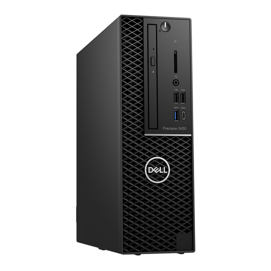
Dell Precision 3430 Small Form Factor Installation Manual
Hide thumbs
Also See for Precision 3430 Small Form Factor:
- Installation manual (6 pages) ,
- Service manual (121 pages) ,
- Setup and specifications manual (34 pages)
Summary of Contents for Dell Precision 3430 Small Form Factor
- Page 1 Dell Precision 3430 Small Form Factor USB Type-C card Installation Guide Regulatory Model: D11S Regulatory Type: D11S004...
- Page 2 A WARNING indicates a potential for property damage, personal injury, or death. © 2018 Dell Inc. or its subsidiaries. All rights reserved. Dell, EMC, and other trademarks are trademarks of Dell Inc. or its subsidiaries. Other trademarks may be trademarks of their respective owners.
-
Page 3: Table Of Contents
Components of an ESD field service kit........................6 ESD protection summary ............................7 Transporting sensitive components..........................7 Lifting equipment ................................ 7 After working inside your computer..........................7 2 USB Type-C..............................8 Installing the USB Type-C card............................8 3 Getting help..............................22 Contacting Dell................................. 22 Contents... -
Page 4: Before You Begin
Damage due to servicing that is not authorized by Dell is not covered by your warranty. Read and follow the safety instructions that came with the product. -
Page 5: Safety Precautions
Due to the increased density of semiconductors used in recent Dell products, the sensitivity to static damage is now higher than in previous Dell products. For this reason, some previously approved methods of handling parts are no longer applicable. -
Page 6: Esd Field Service Kit
• Transporting Sensitive Components – When transporting ESD sensitive components such as replacement parts or parts to be returned to Dell, it is critical to place these parts in anti-static bags for safe transport. Before you begin... -
Page 7: Esd Protection Summary
Transporting sensitive components When transporting ESD sensitive components such as replacement parts or parts to be returned to Dell, it is critical to place these parts in anti-static bags for safe transport. -
Page 8: Usb Type-C
USB Type-C Installing the USB Type-C card Follow the procedure in Before working inside your computer. Remove the side cover: Slide the release latch on the back panel of your system until it gives a click sound to unlock the side cover [1]. b Slide and lift the side cover from the system [2]. - Page 9 Release the hard drive and optical drive module: Disconnect the hard drive data cable and power cable from the connectors on the hard drive [1, 2]. b Slide the release tab to unlock the hard drive and optical module [3]. Unroute the hard drive cables [1] and optical drive cables [2] through the retention clip and HDD-ODD release tab respectively.
- Page 10 d Lift the hard drive and optical module [3] Remove the hard drive and optical drive module: Disconnect the optical drive data cable and optical drive power cable from the connectors on the optical drive [1, 2]. b Slide and lift the hard drive and optical drive module from the system [3]. USB Type-C...
- Page 11 Remove the heat sink with fan: Disconnect the heat sink fan cable from the system board [1]. b Loosen the four captive screws that secure the heat sink [2] and lift it away from the system [3]. NOTE: Loosen the screws in a sequential order (1,2,3,4) as mentioned on the system board. USB Type-C...
- Page 12 To install the USB Type-C card: Remove the filler using a philips screwdriver. USB Type-C...
- Page 13 b Connect the USB Type-C card cable to the connector on the system board [1]. Align and place the USB Type-C card into the slot on the system chassis [2]. USB Type-C...
- Page 14 d Connect the USB Type-C card cable to the connector on the system board [1]. Fasten the two screws to secure the USB Type-C card to the system chassis [2]. USB Type-C...
- Page 15 To install the heat sink: Align the heat sink onto the processor [1]. b Tighten the four captive screws to secure the heat sink assembly to the system board [2]. NOTE: Tighten the screws in a sequential order (1,2,3,4) as mentioned on the system board. Connect the heat sink fan cable to the slot on the system board [3].
- Page 16 To install the hard drive and optical drive module: Insert the tabs on the hard drive and optical drive module into the slot on the system at a 30-degree angle [1]. b Connect the optical drive data cable and power cable to the connectors on the optical drive [2, 3]. Lower the hard drive and optical drive module so that it is placed in its slot [4].
- Page 17 d Route the optical drive data cable and power cable through the retention clips [1]. Route the hard drive data and power cables through the HDD-ODD release tab [2]. USB Type-C...
- Page 18 Slide the release tab to lock the module [1]. g Connect the hard drive data cable and power cable from the connectors on the hard drive [2, 3]. USB Type-C...
- Page 19 To install the front bezel: Align the bezel, and insert the retention tabs on the bezel into the slots on the system. b Press the bezel until the tabs clicks into place. USB Type-C...
- Page 20 To install the side cover: Place the cover on the system and slide the cover until it clicks into place. b The release latch automatically locks the side cover to the system. USB Type-C...
- Page 21 USB Type-C...
-
Page 22: Getting Help
Dell product catalog. Dell provides several online and telephone-based support and service options. Availability varies by country and product, and some services may not be available in your area. To contact Dell for sales, technical support, or customer service issues: Go to Dell.com/support.


