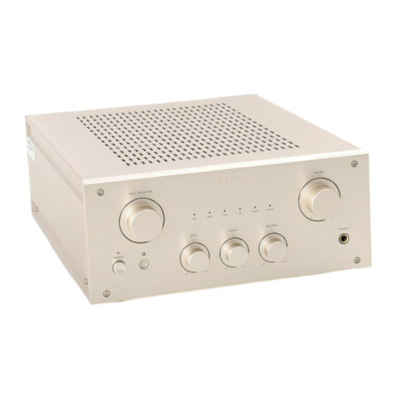
Summary of Contents for Sony TA-F3000
-
Page 1: Service Manual
TA-F3000/F3000ES SERVICE MANUAL AEP Model UK Model TA-F3000ES E Model Chinese Model TA-F3000 Photo: TA-F3000 SPECIFICATIONS INTEGRATED STEREO AMPLIFIER MICROFILM — 1 —... -
Page 2: Table Of Contents
WITH MARK ! ON THE SCHEMATIC DIAGRAMS AND IN THE PARTS LIST ARE CRITICAL TO SAFE OPERATION. REPLACE THESE COMPONENTS WITH SONY PARTS WHOSE PART NUMBERS APPEAR AS SHOWN IN THIS MANUAL OR IN SUPPLEMENTS PUBLISHED BY SONY. — 2 —... -
Page 3: General
SECTION 1 SECTION 2 This section is extracted from instruction manual. GENERAL ELECTRICAL ADJUSTMENTS Bias Adjustment 1. Rotate the semi-fixed resistors (RV501, RV601) for bias adjustment to the MIN side fully (counterclockwise direc- tion). 2. Connect a digital voltmeter to CN501 (TP) and CN601 (TP). -
Page 8: Ic Block Diagrams
3-6. IC BLOCK DIAGRAMS 3-7. IC PIN FUNCTION • IC901 TMP47C200BN-H371 (INPUT CONTROL, LED DRIVE) • Main section Pin No. Pin Name Function IC701 PC1237HA Clock Serial data of EEPROM (X24C01) Data Down OVER LOAD DET VR motor control signal (Active: H, Stop: L-L, Brake: H-H) MUTE OFFSET DET CD input relay signal output... -
Page 9: Exploded Views
SECTION 4 EXPLODED VIEWS NOTE: The components identified by mark ! • The mechanical parts with no reference number in • -XX, -X mean standardized parts, so they may have or dotted line with mark ! are critical the exploded views are not supplied. some difference from the original one. -
Page 10: Chassis Section
4-2. CHASSIS SECTION CNP1 not supplied supplied supplied T801 not supplied not supplied not supplied not supplied not supplied not supplied not supplied The components identified by mark ! or dotted line with mark ! are critical for safety. Replace only with part number speci- fied. -
Page 11: Electrical Parts List
AC OUTLET AC SW SECTION 5 MAIN ELECTRICAL PARTS LIST Note: • SEMICONDUCTORS • Due to standardization, replacements in the parts list The components identified by mark ! In each case, u: µ , for example: may be different from the parts specified in the or dotted line with mark ! are critical uA...: µ... - Page 12 MAIN Ref. No. Part No. Description Remark Ref. No. Part No. Description Remark C713 1-124-910-11 ELECT 47uF D806 8-719-200-82 DIODE 11ES2 C714 1-126-365-51 ELECT 100uF D807 8-719-200-82 DIODE 11ES2 C715 1-115-339-11 CERAMIC CHIP 0.1uF < FUSE > C716 1-115-339-11 CERAMIC CHIP 0.1uF C717 1-115-339-11 CERAMIC CHIP...
- Page 13 MAIN Ref. No. Part No. Description Remark Ref. No. Part No. Description Remark R526 1-216-254-00 CARBON MELF 220K 1/8W Q703 8-729-201-53 TRANSISTOR 2SA1015-GR Q704 8-729-421-22 TRANSISTOR UN2211 R527 1-247-727-11 CARBON 1/2W Q705 8-729-201-53 TRANSISTOR 2SA1015-GR ! R528 1-212-958-00 FUSIBLE 1/2W F Q706 8-729-421-22 TRANSISTOR UN2211 Q707...
- Page 14 MAIN PANEL Ref. No. Part No. Description Remark Ref. No. Part No. Description Remark R723 1-216-699-11 METAL CHIP 100K 0.5% 1/10W D905 8-719-313-50 DIODE SEL6810A-TH12 (TAPE) R724 1-208-810-11 METAL GLAZE 1/10W R725 1-208-812-11 METAL GLAZE 1/10W D906 8-719-313-50 DIODE SEL6810A-TH12 (MD) R726 1-208-453-41 METAL GLAZE 4.7K...
- Page 15 PANEL PHONO Ref. No. Part No. Description Remark Ref. No. Part No. Description Remark R936 1-216-295-91 CONDUCTOR, CHIP (2012) < TRANSISTOR > R937 1-216-295-91 CONDUCTOR, CHIP (2012) R938 1-216-295-91 CONDUCTOR, CHIP (2012) Q101 8-729-354-52 TRANSISTOR 2SC2545 R939 1-216-295-91 CONDUCTOR, CHIP (2012) Q102 8-729-354-52 TRANSISTOR 2SC2545 R940...
- Page 16 TA-F3000/F3000ES TONE Ref. No. Part No. Description Remark Ref. No. Part No. Description Remark < IC > MISCELLANEOUS ************* IC905 8-749-923-43 IC GP1U57XB 1-777-740-11 WIRE (FLAT TYPE) (4 CORE) 1-777-739-11 WIRE (FLAT TYPE) (9 CORE) ************************************************************** 1-506-113-00 SHORT PLUG 1-663-766-11 TONE BOARD...


