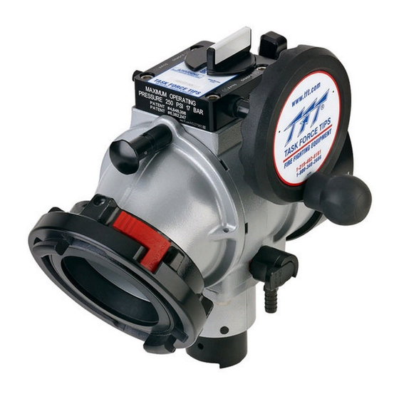
Task Force Tips Ball Intake Valve Instructions For Safe Operation And Maintenance
Hide thumbs
Also See for Ball Intake Valve:
Table of Contents
Advertisement
Quick Links
INSTRUCTIONS FOR SAFE OPERATION AND MAINTENANCE
WARNING
TASK FORCE TIPS, Inc.
www.tft.com
©Copyright Task Force Tips, Inc. 2002-2004
MANUAL: Ball Intake Valve™
Read instruction manual before use. Operation of this device without
understanding the manual and receiving proper training is a misuse of this
equipment. A person who has not read and understood all operating and safety
instructions is not qualified to operate the Ball Intake Valve.
This instruction manual is intended to familiarize firefighters and maintenance
personnel with the operation, servicing and safety procedures associated with
the Ball Intake Valve.
This manual should be kept available to all operating and maintenance
personnel.
www.tft.com
®
1-219-462-6161
1-800-348-2686
A1306
2800 East Evans Avenue • Valparaiso , IN 46383-6940
800-348-2686 • 219-462-6161 • Fax 219-464-7155
OPERATING RANGE:
Pressure Max 250 PSI
Pressure Min Full Vac.
Hydrostatic
Proof Test:
900 PSI
LIA-200 March 17, 2004 Rev 5
Advertisement
Table of Contents

Summary of Contents for Task Force Tips Ball Intake Valve
- Page 1 A person who has not read and understood all operating and safety instructions is not qualified to operate the Ball Intake Valve. This instruction manual is intended to familiarize firefighters and maintenance personnel with the operation, servicing and safety procedures associated with the Ball Intake Valve.
-
Page 2: Table Of Contents
CORROSION 8.0 DRAWINGS AND PARTS LISTS USE WITH SALT WATER MAINTENANCE INSTALLATION MOUNTING ON TRUCK 10.0 BALL INTAKE VALVE PRESSURE LOSS CHANGING HANDWHEEL TO LEFT SIDE 11.0 WARRANTY INTAKE ELBOW VALVE POSITION INDICATOR STORZ SUCTION GASKET REQUEST 1.0 MEANING OF SIGNAL WORDS A safety related message is identified by a safety alert symbol and a signal word to indicate the level of risk involved with a particular hazard. -
Page 3: General Information
In the past some valves were made of bare aluminum. Task Force Tips is using a three-step process to fight corrosion. The cast aluminum parts in this valve have been impregnated to fill the microscopic pores in the cast aluminum. The parts are then hard anodized, and finally powder coated, inside and out, to help prevent corrosion. -
Page 4: Use
7.2 RELIEF VALVE FLOW vs. PRESSURE CURVE PRESSURE RELIEF VALVE PERFORMANCE 700 FLOW (LPM) Adjusting Screw 200 PSI SETTING 125 PSI SETTING Relief Valve Discharge Opening 50 PSI SETTING 200 FLOW (GPM) ©Copyright Task Force Tips, Inc. 2002-2004 LIA-200 March 17, 2004 Rev 5... - Page 5 8.0 DRAWINGS AND PARTS LISTS 62 63 45 46 ©Copyright Task Force Tips, Inc. 2002-2004 LIA-200 March 17, 2004 Rev 5...
- Page 6 8.0 DRAWINGS AND PARTS LISTS Ball Intake Valve Parts List Index Description Part # BGIV BODY - POWDER COAT A1015 O-RING-161 5 1/2 ID X 3/32 C/S VO-161 BACK RING STAINLESS STEEL A1201S VALVE SEAT A1520 PLASTIC STRIP 7.00" A1290...
- Page 7 O-RING-231 2-5/8 ID 1/8 C/S VO-231 QUAD RING 422 1.5 ID X 1/8 C/S VOQ-4222 SPRING SEAT A1166 RELIEF SPRING A1170 SMALLEY RING V4210 ADJUSTING SCREW A1167 SPRING HOUSING A1164 ©Copyright Task Force Tips, Inc. 2002-2004 LIA-200 March 17, 2004 Rev 5...
- Page 8 11.0 WARRANTY Task Force Tips, Inc., 2800 East Evans Avenue, Valparaiso, Indiana 46383 ("TFT") warrants to the original purchaser of its Ball Intake Valve ("equipment"), and to anyone to whom it is transferred, that the equipment shall be free from defects in material and workmanship during the five (5) year period from the date of purchase.


