Advertisement
Quick Links
TASK FORCE TIPS
TASK FORCE TIPS
INSTRUCTIONS FOR SAFE OPERATION AND MAINTENANCE
This instruction manual is intended to familiarize firefighters and maintenance personnel with the operation, servicing and
safety procedures associated with the Pressure Relief Valve.
This manual should be kept available to all operating and maintenance personnel.
Read instruction manual before use. Operation of this device without understanding the manual and
WARNING
receiving proper training is a misuse of this equipment. A person who has not read and understood all
operating and safety instructions is not qualified to operate the Pressure Relief Valve.
1.0 MEANING OF SAFETY WORDS
A safety related message is identified by a safety alert symbol and a signal word to indicate the level of risk involved with a particular
hazard. Per ANSI standard Z535.4-1998 the definitions of the three signal words are as follows:
DANGER indicates an imminently hazardous situation which, if not avoided, will result in death or serious injury.
DANGER
WARNING indicates a potentially hazardous situation which, if not avoided, could result in death or serious injury.
WARNING
CAUTION indicates a potentially hazardous situation which, if not avoided, may result in minor or moderate injury.
CAUTION
2.0 GENERAL INFORMATION
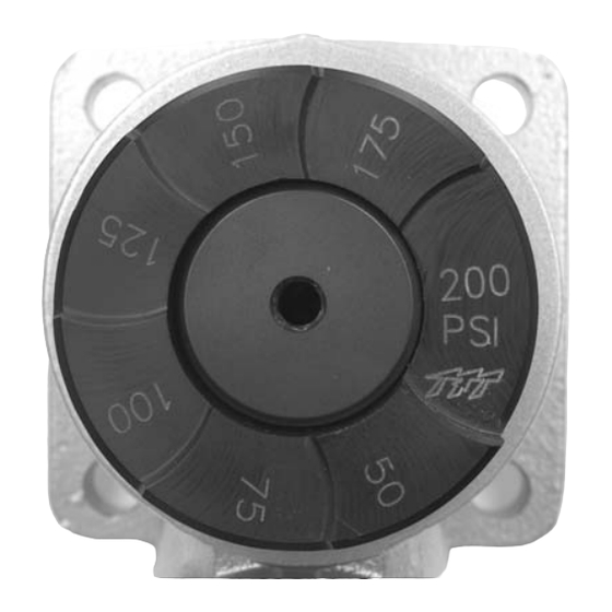
The Pressure Relief Valve may be set to any pressure between 50 and 200 p.s.i.. Its function is to protect the pump and the supply hose
from excess pressure. The relief valve may be mounted with its opening facing the front, back, right or left. A section of tubing or pipe
may be mounted on the round spout to route the water in any direction. To install the Pressure Relief Valve;
1) Install the O-ring in the groove on the Pressure Relief Valve.
2) Install four 7/16" bolts through the Pressure Relief Valve flange. Use a drop of thread locking compound on the threads of the bolts to
prevent them from coming loose.
3.0 RELIEF VALVE
To set the relief valve pressure turn the adjusting screw on the relief valve housing until the surface of the screw is
desired pressure.
Do not cap or plug discharge opening.
TASK FORCE TIPS, INC.
www.tft.com
©Copyright Task Force Tips, Inc. 2004
PRESSURE
SETTING
Manual:
Pressure Relief Valve
50 PSI
Adjusting
Screw
2800 East Evans Avenue, Valparaiso, IN 46383-6940
800-348-2686 • 219-462-6161 • Fax 219-464-7155
even with the
125 PSI
200 PSI
LIA-202 October 4, 2004 Rev 0
Advertisement

Summary of Contents for Task Force Tips Pressure Relief Valve
- Page 1 2.0 GENERAL INFORMATION The Pressure Relief Valve may be set to any pressure between 50 and 200 p.s.i.. Its function is to protect the pump and the supply hose from excess pressure. The relief valve may be mounted with its opening facing the front, back, right or left. A section of tubing or pipe may be mounted on the round spout to route the water in any direction.
- Page 2 200 PSI SETTING 125 PSI SETTING 50 PSI SETTING FLOW (GPM) PRESSURE RELIEF VALVE PERFORMANCE 5.0 DRAWING AND PARTS LIST Pressure Relief Valve 50 - 200 psi Index Description Part # 1/2-13 X 1.0 BUTTON HEAD CAP SCREW VT50-13BH1.0 O-RING-236 3-1/4 ID 1/8 C/S...


