Sign In
Upload
Manuals
Brands
Bosch Manuals
Media Converter
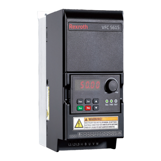
rexroth VFC 615 Series
Bosch rexroth VFC 615 Series Manuals
Manuals and User Guides for Bosch rexroth VFC 615 Series. We have
1
Bosch rexroth VFC 615 Series manual available for free PDF download: Operating Instructions Manual
Bosch rexroth VFC 615 Series Operating Instructions Manual (616 pages)
Frequency Converter
Brand:
Bosch
| Category:
Media Converter
| Size: 29.79 MB
Table of Contents
Table of Contents
19
1 Safety Instructions for Electric Drives and Controls
33
Definitions of Terms
33
Explanation of Signal Words and the Safety Alert Symbol
35
General Information
36
Using the Safety Instructions and Passing Them on to Others
36
Requirements for Safe Use
36
Hazards by Improper Use
38
Instructions with Regard to Specific Dangers
39
Protection against Contact with Electrical Parts and Housings
39
Protective Extra-Low Voltage as Protection against Electric Shock
40
Protection against Dangerous Movements
40
Protection against Magnetic and Electromagnetic Fields During Operation and Mounting
42
Protection against Contact with Hot Parts
43
Protection During Handling and Mounting
43
2 Important Directions for Use
44
Appropriate Use
44
Inappropriate Use
44
3 Documentation Information
44
About this Documentation
44
Relevant Software
45
Reference
46
4 Delivery and Storage
46
Product Identification
46
Packing Nameplate
46
Product Nameplate
48
Visual Inspection
49
Scope of Supply
49
Transport of the Components
50
Storage of the Components
50
5 Drive System Overview
51
6 Frequency Converter Overview
52
Product Features
52
Input
52
Output
52
V/F Control Performance
53
SVC Control Performance
53
Main Functions
54
Communication
54
Operating Panel
55
Protection
55
Conditions
56
Technical Data
57
Electric Data
57
Derating of Electric Data
60
Derating and Ambient Temperature
60
Derating and Mains Voltage
61
Derating and Carrier Frequency
62
Maximum Length of Motor Cables
67
Minimum Inductance between Two Motor Terminals
67
7 Frequency Converter Mounting
67
Installation Conditions
67
Heat Dissipation
69
Air Flow of Fans
71
Figures and Dimensions
73
Standard Models
73
Wall-Through Models
78
8 Frequency Converter Wiring
84
Wiring Diagram
84
Cable Specifications
86
Power Cables
86
Cable Specification for International Without USA / Canada
86
Cable Specification for USA / Canada
89
Dimensioning Variables of the Table Values
90
Control Cables
93
Terminals
94
Power Terminals
94
Power Terminals Figure
94
Power Terminals Description
95
Notes on DC-Bus Terminals
96
Control Terminals
102
Control Terminals Figure
102
Control Terminals Description
103
Digital Input NPN / PNP Wiring
105
Digital Output Do1A, Do1B Load Pull-Up / Pull-Down Wiring
106
Analog Input Terminals (AI1, AI2, EAI, +10 V, +5 V, Earth and GND)
107
Relay Output Terminals
107
Notes on DC_IN Terminal
109
9 Electromagnetic Compatibility (EMC)
110
EMC Requirements
110
General Information
110
The Electromagnetic Compatibility (EMC) or Electromagnetic Interference (EMI) Includes the Following Requirements
110
Noise Immunity in the Drive System
110
Basic Structure for Noise Immunity
110
Minimum Immunity Requirements for Pdss Intended for Use in the Second Environment
112
Evaluation Criterion
112
Noise Emission of the Drive System
113
Ensuring the EMC Requirements
117
EMC Measures for Design and Installation
119
Rules for Design of Installations with Drive Controllers in Compli- Ance with EMC
119
EMC-Optimal Installation in Facility and Control Cabinet
121
Control Cabinet Mounting According to Interference Areas - Exem- Plary Arrangements
122
Design and Installation in Area a - Interference-Free Area of Control Cabinet
123
Design and Installation in Area B - Interference-Susceptible Area of Control Cabinet
125
Design and Installation in Area C - Strongly Interference-Susceptible Area of Control Cabinet
126
Ground Connections
127
Installing Signal Lines and Signal Cables
128
General Measures of Radio Interference Suppression for Relays, Contactors, Switches, Chokes and Inductive Loads
129
10 Operating Panel and Dust Cover
129
LED Panel
129
LED Display
130
Dust Cover
131
LED Indicator
132
Operating Descriptions
133
Fast Access to Parameters with Button Combinations
134
Digit Shifting Function for Modification of Parameter Values
135
LCD Panel
136
LCD Panel Introduction
136
Operating Example
137
11 Quick Start
138
Checklist before Quick Start
138
Step 1: Check Application Conditions
138
Step 2: Check Mounting Conditions
138
Step 3: Check the Wiring
138
Quick Start Parameters
139
Control the Motor
140
Motor Parameters Auto-Tuning
141
Possible Errors During Quick Start and Respective Solutions
142
Restoring Parameters to Factory Defaults
142
12 Functions and Parameters
143
B0: Basic System
143
Access Authority Setting
143
Parameter Initialization
145
Parameter Copy
146
Parameter Set Switch
148
Password Protection
150
High Frequency Mode
151
C0: Power Control
152
Control Mode Selection
152
Normal Duty / Heavy Duty Setting
153
Carrier Frequency Setting
154
PWM Mode
160
Automatic Voltage Stabilization
161
Brake Chopper Control
162
Overvoltage Suppression
163
Overvoltage Prevention Mode
166
Stall Overvoltage Prevention
167
Stall Overcurrent Prevention
168
Phase Loss Protection
170
Converter Overload Pre-Warning
171
Power Loss Ride-Through
172
Fan Control and Maintenance
176
C1: Motor and System
178
Motor Type Selection
178
Motor Parameter Tuning
178
Motor Name Plate Data
182
Motor Internal Data
185
Motor Thermal Model
187
Motor Overload Pre-Warning
189
Motor Thermal Sensor Selection
191
C2: V/F Control
194
V/F Curve Setting
194
Slip Compensation
200
Hz Output Mode
200
Torque Boost Setting
201
Heavy Load Stabilization
204
Light Load Oscillation Damping
204
Current Limitation
205
C3: Vector Control
206
Speed Loop Setting
206
Speed Observer Mode
207
Current Loop Setting
207
Torque Limitation
208
Speed Monitor
209
Fieldweakening Control for PMSM
210
Torque Control
211
Initial Angle Detection
216
SVC Switch Point
216
Speed Damping Factor for SVC
217
D0: Basic Monitoring
218
D1: Enhanced Monitoring
220
E0: Set Point and Control
221
Frequency Setting Source
221
Run Command Source
226
Digital Setting Frequency
227
Frequency Limitations
228
Direction Control
230
Acceleration and Deceleration Setting
232
Start Mode Configuration
234
Power Loss Restart
239
Stop Mode Configuration
240
Stop DC-Braking
241
Overexcitation Braking
245
Emergency Stop
246
Jog Function
247
Skip Frequency
249
E1: Input Terminal
253
Digital Input Configuration
253
2- and 3-Wire Control
258
Digital Input Frequency Change Function
263
Pulse Input Configuration
265
Analog Input Configuration
266
Motor Temperature Sensor Channel
269
E2: Output Terminal
270
Digital Output Configuration
270
Pulse Output Setting
273
Relay Output
276
Analog Output Configuration
279
Frequency Detection Function
282
Pulse Counter Function
284
E3: Multi-Speed and Simple PLC
286
Simple PLC and Multi-Speed Setting
286
Parameters
286
Multi-Speed Setting
289
Simple PLC Setting
295
Stop and Pause Simple PLC Control
297
Indication of Simple PLC Status
298
E4: PID Control
300
PID Control Setting
300
Parameters
300
Selecting the Reference and Feedback
302
PID Feedback Polarity
303
Control Loop Configuration
304
PID Regulation Mode Setting
305
PID Feedforward Control
305
PID Deactivation by Digital Input
306
PID Status Indication
306
E5: Extended Application Functions
308
High Resolution Current Display
308
Speed Display Scaling
308
Pump Dry and Leakage Protection
309
Sleep Function
310
E8: Standard Communication
312
Modbus Protocol
312
Brief Introduction
312
Protocol Description
312
Modbus Interface
314
Modbus Function and Message Format
314
Communication Mapping Register Address Distribution
322
Modbus Communication Example
331
Special Notes
332
Communication Networking
333
Communication Selection
335
Communication Error Reaction
336
Modbus Settings
338
Setting the Data Transmission Rate
338
Setting the Data Format
338
Setting the Local Address
338
Setting Command Signal Type
339
Setting Modbus Transmission Mode
339
E9: Error Log and Automatic Error Reset
340
Automatic Error Reset
340
Related Parameters
340
Detailed Description
340
List of Errors with Automatic Error Reset Capability
340
Error Log
342
F0: ASF Basic Settings
345
ASF Status
345
ASF Function Description
345
ASF Parameter
345
ASF Management
346
ASF Diagnosis
347
ASF Command Values
349
H0: Extension Card General Settings
350
Status and Control Words
350
Extension Card Identification
355
H1: PROFIBUS Settings
356
PROFIBUS Basic Settings
356
PROFIBUS Card LED
357
PROFIBUS Output PZD Setting
358
Input PZD Setting
361
PROFIBUS Protocol
362
Protocol Description
362
PROFIBUS Function
362
Requirements for PROFIBUS Link Cable
363
Relationship between Communication Rate and Cables
363
EMC Measures
364
Periodical Data Communication
364
Communication Parameter Configuration
372
H2: Canopen Card Parameters
374
General Introduction
374
LED Status Introduction
374
Converter Configuration
376
Overview
376
COB-Identifiers
376
Object Dictionary
377
Process Data Objects (PDO)
381
Process Data Objects (PDO) Configuration
383
Service Data Objects (SDO)
387
Network Management Objects (NMT)
388
Emergency Service (EMCY)
390
Synchronisation Service (SYNC)
392
Device Profile
394
Related Communication Parameters
406
Canopen Option Card Parameters
408
H8: IO&IO Plus Card Parameters
409
IO & IO Plus Card Analog Input Configuration
409
IO & IO Plus Card Analog Output Configuration
416
IO & IO Plus Card Digital Input Configuration
419
IO & IO Plus Card Digital Output Configuration
424
IO Card Relay Output Configuration
427
I/O & I/O Plus Card Diagnosis
429
H9: Relay Card Parameters
430
Relay Card Output Configuration
430
U0: General Panel Parameters
434
U1: LED Panel Parameters
435
U2: LCD Panel Parameters
436
13 Diagnosis
437
Display of LED Characters
437
Status Code
437
Warning Code
439
Error Code
440
Error 1 (OC-1), Error 2 (OC-2), Error 3 (OC-3) : Overcurrent
440
Error 4 (OE-1), Error 5 (OE-2), Error 6 (OE-3) : Overvoltage
441
Error 8 (UE-1): Undervoltage During Run
441
Error 9 (SC): Surge Current or Short Circuit
441
Error 10 (IPH.L): Input Phase Loss
442
Error 11 (OPH.L): Output Phase Loss
442
Error 12 (ESS-): Soft Start Error
442
Error 20 (OL -1): Converter Overload
442
Error 21 (OH): Converter over Temperature
443
Error 23 (FF): Fan Failure
443
Error 24 (Pdr): Pump Dry
444
Error 25 (Col -): Command Value Lost
444
Error 30 (OL -2): Motor Overload
444
Error 31 (Ot): Motor over Temperature
445
Error 32 (T-Er): Motor Parameter Tuning Error
445
Error 33 (Ade-): Motor Angle Detection Error
445
Error 35 (SPE-): Speed Control Loop Error
446
Error 38 (Aibe): Analog Input Broken Wire Detection
446
Error 39 (EPS-): DC_IN Power Supply Error
446
Error 40 (Dir1): Forward Running Lock Error
446
Error 41 (Dir2): Reverse Running Lock Error
447
Error 42 (E-St): Terminal Error Signal
447
Error 43 (FFE-): Firmware Version Mismatch
447
Error 44 (Rs-): Modbus Communication Error
447
Error 45 (E.par): Parameter Settings Invalid
448
Error 46 (U.par): Unknown Parameter Restore Error
448
Error 48 (Ida-): Internal Communication Error
448
Error 49 (Idp-): Internal Parameter Error
448
Error 50 (Ide-): Converter Internal Error
449
Error 51 (Ocd-): Extension Card Internal Error
449
Error 52 (Occ): Extension Card Pdos Configuration Error
449
Error 53 (Fdi-): no Valid Process Data
450
Error 54 (Pce-): Remote Control Communication Error
450
Error 55 (Pbre): Parameter Backup / Restore Error
450
Error 56 (Pref): Parameter Restore Error after Firmware Update
450
Error 60 (ASF-): Application Firmware Error
451
Error 61
451
Error Handling
452
Restarting after Power Loss
452
Automatic Error Reset
453
Error Reset by Digital Input
454
14 Communication
454
Brief Introduction
454
Basic Communication Settings
454
Selection of the Communication Protocol
454
Setting the Data Transmission Rate
455
Setting the Data Format
456
Setting the Local Address
456
Setting Command Signal Type
456
Communication Disruption and Response
457
Modbus Protocol
458
Protocol Description
458
Brief Introduction
458
Transmission
459
Modbus Interface
460
Modbus Function and Message Format
460
Supported Functions
460
Function Example
462
Function 0X06: Write One Register Word
463
Function 0X08: Diagnostics
464
Function 0X10: Write N Register Words, Range: 1
465
Function 0X17: Read/Write N Register Words, Range: 1
465
Error Code and Exception Code
467
Communication Mapping Register Address Distribution
468
Frequency Converter Parameter Address
468
Frequency Converter Register Address
469
Communication Control Register (0X7F00)
470
Communication State Register (0X7Fa0)
471
Additional Status Register (0X7Fa1)
472
Fault Status Register (0X7Fb0)
473
Communication Frequency Setting Register (0X7F01)
474
Torque Setting Register (0X7F02)
474
Torque FWD Limitation Register (0X7F03)
474
Torque REV Limitation Register (0X7F04)
475
Speed Limitation Register (0X7F05)
475
Modbus Communication Example
476
Special Notes
477
Communication Networking
478
Networking
478
Recommendations on Networking
478
PROFIBUS Protocol
479
Protocol Description
479
PROFIBUS Function
479
Requirements for PROFIBUS Link
480
Relationship between Communication Rate and Cables
480
EMC Measures
481
Periodical Data Communication
481
PPO Telegram Type
481
PKW Parameter Area
482
PZD Process Data Area
485
Communication Parameter Configuration
489
Communication Related Parameter Settings
489
Parameter Configuration of Master
490
GSD File
491
15 Accessories
491
Optional Accessories
491
Operating Panel
493
Panel Mounting Plate
493
Function Description
493
Recommended Opening Dimensions at Control Cabinet
493
Mounting the Plate and the Operating Panel
494
Step 1
494
Step 2
494
Step 3
494
Step 4
495
Communication Cable for Control Cabinet
496
Extension Card Module
496
Dimensions of Extension Card Module
496
Extension Card Module Mounting
496
Extension Module Mounting
497
I/O Module
500
I/O Card
500
I/O Card Terminals Label
500
I/O Card Terminals Descriptions
500
I/O Card Terminals Wiring
501
Relay Card
502
Relay Card Terminals Label
502
Relay Card Terminals Descriptions
502
Relay Card Terminals Wiring
502
I/O Plus Card
502
Terminals Mapping
502
Terminals Description
502
Wiring
504
Communication Module
505
PROFIBUS Interface
505
PROFIBUS Card LED
506
Canopen Card
507
Interface Introduction
507
Cable and Connection
508
Plug-In Connector for Control Section
509
External Mains EMC Filter
509
External Mains EMC Filter Type
509
Technical Data
511
Dimensions
511
Electric Data
519
External Brake Resistor
522
Braking Ratio
522
Brake Resistor Type for Braking Ratio of
523
Brake Resistor Type for Braking Ratio of
527
Brake Resistor Dimensions
529
Installation of Brake Resistor
532
Shielding Connector
533
16 Maintenance
539
Safety Instructions
539
Daily Inspection
540
Periodic Inspection
541
Expired Replacement
542
Removable Components Maintenance
543
Construction Overview
543
Disassembly of the Operating Panel
544
Disassembly of Fans
545
Service and Support
546
17 Service and Support
547
Environmental Protection
547
Disposal
547
18 Environmental Protection and Disposal
547
Environmental Protection and Disposal
547
19 Appendix
548
Appendix I: Abbreviations
548
Appendix II: Type Coding
550
Frequency Converter Type Coding
550
Operating Panel Type Coding
551
Panel Mounting Plate Type Coding
551
Communication Cable for Control Cabinet Type Coding
552
Extension Accessories Type Coding
552
External EMC Filter Type Coding
554
External Brake Resistor Type Coding
555
Shielding Connector Type Coding
556
Appendix III: Parameter List
557
Terminology and Abbreviation in Parameter List
557
Group B: System Parameters
558
B0: Basic System Parameters
558
Group C: Power Parameters
559
C0: Power Control Parameters
559
C1: Motor and System Parameters
563
C2: V/F Control Parameters
565
C3: Vector Control Parameters
567
Group E: Function Control Parameters
571
E0: Set Point and Control Parameters
571
E1: Input Terminal Parameters
574
E2: Output Terminal Parameters
577
E3: Multi-Speed and Simple PLC Parameters
580
E4: PID Control Parameters
583
E5: Extended Function Parameters
585
E8: Standard Communication Parameters
586
E9: Protection and Error Parameters
587
Group F0: ASF Parameters
591
Group H: Extension Card Parameters
591
H0: Extension Card General Parameters
591
H1: PROFIBUS Card Parameters
592
H2: Canopen Card Parameters
594
H8: I/O Card Parameters
596
H9: Relay Card Parameters
600
Group U: Panel Parameters
603
U0: General Panel Parameters
603
U1: LED Panel Parameters
603
U2: LCD Panel Parameters
604
Group D0: Monitoring Parameters
606
Group D1: Enhanced Monitoring
607
Appendix IV: Certification
608
Index
609
Advertisement
Advertisement
Related Products
Bosch Rexroth VFC 3210
Bosch rexroth VFC 3615
Bosch rexroth VFC 5615
Bosch VJD-3000
Bosch VIP X1
Bosch VIP-XDHD
Bosch VJM-4016
Bosch VJD-8000
Bosch VJD-8000-N
Bosch VIP-X16XF-E
Bosch Categories
Dishwasher
Washer
Oven
Power Tool
Dryer
More Bosch Manuals
Login
Sign In
OR
Sign in with Facebook
Sign in with Google
Upload manual
Upload from disk
Upload from URL