Sign In
Upload
Manuals
Brands
Cisco Manuals
Multi-service Platforms
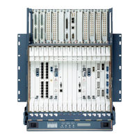
ONS 15310-MA SDH
Cisco ONS 15310-MA SDH Manuals
Manuals and User Guides for Cisco ONS 15310-MA SDH. We have
3
Cisco ONS 15310-MA SDH manuals available for free PDF download: Procedure Manual, Troubleshooting Manual
Cisco ONS 15310-MA SDH Procedure Manual (632 pages)
Brand:
Cisco
| Category:
Network Hardware
| Size: 18.97 MB
Table of Contents
Table of Contents
3
Cisco ONS 15310-MA SDH Procedure Guide, Release 9.1 and Release
20
Table of Contents
21
Before You Begin
49
Chapter 1 Install the Cisco on 15310-MA SDH
51
Tools Needed
52
NTP- H150 Install the Shelf Assembly
53
NTP- H169 Install the Cable Management Bracket
54
Figure 1-1 Installing the Standard Cable Management Bracket
55
Figure 1-2 Installing the Extended Cable Management Bracket
56
Figure 1-3 Blank Sheet Metal Covers
56
NTP- H166 Remove the Blank Sheet Metal Covers
57
NTP- H167 Install the Eias
58
Figure 1-4 High-Density EIA Installation
59
NTP- H151 Install the Power and Ground
60
NTP- H189 View Shelf Temperature
62
Figure 1-6 Installing the Fan-Tray Air Filter
63
NTP- H153 Install the 15310E-CTX-K9 Cards
64
Figure 1-8 Installing a 15310E-CTX-K9 Card
66
NTP- H154 Install the Ethernet Cards
67
NTP- H187 Install STM-N Cards and Connectors
68
Table 1-1 Maximum Bandwidth by Shelf Slot for the MRC-12 in Different Cross-Connect Configurations
70
NTP-H155 Install the Electrical Cards
71
NTP-H156 Install the Filler Cards
73
NTP-H157 Install Wires to Alarm, Timing, Craft, LAN, and UDC Pin Connections
74
NTP-H158 Install the Electrical Cables
75
NTP-H159 Install and Remove Sfps
76
NTP-H160 Install Optical Cables
77
Table 1-2 Optical Transmit and Receive Levels
78
NTP-H164 Perform the Shelf Installation Acceptance Test
79
Table 1-3 ONS 15310-MA SDH Shelf Installation Task Summary
79
NTP-H161 Preprovision an SFP Slot
80
NTP-H162 Preprovision a Card Slot
81
NTP-H163 Remove and Replace a Card
81
NTP-H168 Install the Front Door
83
Figure 1-9 Installing the Front Door
84
NTP-H190 Install the Rear Cover
85
Figure 1-10 Removing the Panhead Screws
86
Figure 1-11 Installing the Rear Cover
87
Before You Begin
89
NTP-H13 Set up Computer for CTC
89
NTP-H14 Set up TL1 Session for Local Craft Connection to the Node
91
Chapter 2 Connect the PC and Log into the GUI
91
NTP- H15 Set up a CTC Computer for a Corporate LAN Connection to the Node
92
NTP- H16 Set up a Remote Access Connection to the Node
93
NTP-H17 Log into the GUI
93
Figure 16-19 Login Node Group
94
NTP-H147 Use the CTC Launcher Application to Manage Multiple ONS Nodes
95
Before You Begin
97
NTP-H148 Verify Card and SFP Installation
98
Chapter 3 Turn up a Node
98
NTP-H19 Create Users and Assign Security
99
NTP-H20 Set up Name, Date, Time, and Contact Information
99
NTP-H21 Set up CTC Network Access
102
NTP-H177 Set up the ONS 15310-MA SDH in EMS Secure Access
103
NTP-H22 Set up the ONS 15310-MA SDH for Firewall Access
103
Figure 3-2 CTC Computer and ONS 15310-MA Sdhs Residing Behind Firewalls
104
ONS 15310-MA SDH Nodes Residing Behind a Firewall
104
NTP-H276 Create FTP Host
105
NTP-H142 Create Protection Groups for ONS 15310-MA SDH
106
NTP-H23 Set up Timing
106
Table 3-1 Protection Types
107
NTP-H25 Set up SNMP
108
NTP-H131 Provision OSI
109
NTP-H180 Provision Node for Snmpv3
110
NTP-H181 Provision Node to Send Snmpv3 Traps
111
NTP-H182 Manually Provision a GNE/ENE to Manage an ENE Using Snmpv3
111
NTP-H183 Automatically Provision a GNE to Manage an ENE Using Snmpv3
112
NTP-H184 Manually Provision a GNE/ENE to Send Snmpv3 Traps from an ENE Using Snmpv3
113
Snmpv3
113
NTP- H185 Automatically Provision a GNE/ENE to Send Snmpv3 Traps from an ENE Using Snmpv3
114
Before You Begin
115
NTP-H26 Verify Node Turn-Up
116
NTP-H27 Provision a Point-To-Point Network
117
Chapter 4 Turn up a Network
117
Figure
118
NTP-H28 Point-To-Point Network Acceptance Test
118
Figure
119
Figure 4-1 ONS 15310-MA SDH Linear ADM Configuration
120
NTP-H29 Provision a Linear ADM Network
120
NTP-H30 Linear ADM Network Acceptance Test
121
NTP-H31 Provision Path Protection Nodes
123
Figure 4-2 ONS 15310-MA SDH Path Protection Fiber Connection Example
124
NTP-H32 Path Protection Acceptance Test
125
NTP-H33 Provision an Open-Ended Path Protection Configuration
127
Figure 4-3 ONS 15310-MA SDH Open-Ended Path Protection Configurations Fiber Connection Example
128
NTP-H34 Open-Ended Path Protection Acceptance Test
129
Figure 4-4 Traditional Path Protection DRI Fiber Connection Example
133
Figure 4-5 Integrated Path Protection DRI Example
135
Sdh
137
CHAPTER 5 Create Circuits and VC Low-Order Path Tunnels
138
Before You Begin
138
Table 5-1 ONS 15310-MA SDH Circuit Options
138
C H a P T E R 5 Create Circuits and VC Low-Order Path Tunnels
138
NTP-H36 Verify Network Turn-Up
141
NTP-H37 Create an Automatically Routed E1 Circuit
141
Figure
142
Figure 5-1 Setting Circuit Attributes for a E1 Circuit
143
NTP-H38 Create a Manually Routed E1 Circuit
145
NTP-H39 Create a Unidirectional E1 Circuit with Multiple Drops
148
NTP-H40 Create an Automatically Routed DS-3 or E3 Circuit
151
NTP-H41 Create a Manually Routed DS-3 or E3 Circuit
154
NTP-H42 Create a Unidirectional DS-3 or E3 Circuit with Multiple Drops
157
NTP-H46 Test Electrical Circuits
160
NTP-H43 Create an Automatically Routed VC Low-Order Path Tunnel
161
NTP-H44 Create a Manually Routed VC Low-Order Path Tunnel
164
NTP-H45 Create a VC Low-Order Path Aggregation Point
165
NTP-H47 Create an Automatically Routed Optical Circuit
168
NTP-H48 Create a Manually Routed Optical Circuit
171
NTP-H49 Create a Unidirectional Optical Circuit with Multiple Drops
174
NTP-H50 Test Optical Circuits
177
NTP-H51 Create an Automatically Routed VCAT Circuit
178
NTP-H52 Create a Manually Routed VCAT Circuit
183
NTP-H55 Create Overhead Circuits
186
NTP-H140 Create a Server Trail
187
NTP-H179 Create an Overlay Ring Circuit
188
NTP-C186 Manually Create a CCAT or VCAT Circuit on the CE-MR-10 Card
191
NTP-H188 Create an Ethernet Drop and Continue Circuit
194
Before You Begin
197
Chapter 6 Manage Circuits
197
Figure
197
NTP-H69 Locate and View Circuits
198
NTP-H70 View Cross-Connect Resource Usage
198
NTP-H71 Modify and Delete Circuits
199
NTP-H72 Modify and Delete Overhead Circuits and Server Trails
200
NTP-H73 Create a Monitor Circuit
200
NTP-H144 Create a J0 Section Trace
201
NTP-H74 Create a J1 Path Trace
203
NTP-H75 Create a J2 Path Trace
203
NTP-H129 Bridge and Roll Traffic
206
NTP-H76 Reconfigure Circuits
207
NTP-H77 Merge Circuits
207
Before You Begin
209
Chapter 7 Monitor Performance
209
NTP-H64 Change the PM Display
210
NTP-H65 Monitor Electrical Performance
211
NTP-H66 Monitor Optical Performance
212
NTP-H67 Monitor Ethernet Performance
212
NTP-H68 Create or Delete Ethernet RMON Thresholds
213
NTP-H175 Enable or Disable Autopm
214
Before You Begin
215
Manage Alarms
215
NTP-H56 Document Existing Provisioning
216
NTP-H57 View Alarms, History, Events, and Conditions
216
NTP-H58 Delete Cleared Alarms from Display
217
Chapter 8 Manage Alarm
217
Figure 8-1 ONS 15310-MA SDH Node View Conditions Window
218
NTP-H59 View Alarm-Affected Circuits
219
NTP-H60 Create, Download, and Assign Alarm Severity Profiles
220
NTP-H61 Enable, Modify, or Disable Alarm Severity Filtering
221
NTP-H62 Suppress Alarms or Discontinue Alarm Suppression
221
NTP-H63 Provision External Alarms and Controls
222
Figure 8-3 External Alarms for the ONS 15310-MA SDH
223
Before You Begin
225
Chapter 9 Change Port Settings
225
NTP-H86 Modify Line Settings and PM Parameter Thresholds for Electrical Ports
226
NTP-H87 Modify Line Settings and PM Parameter Thresholds for Optical Ports
226
NTP-H130 Manage Pluggable Port Modules
227
NTP-H172 Provision the Soak Timer for an ML-100T-8 Card
228
NTP-H92 Change Card or PPM Service State
228
Before You Begin
231
Chapter 10 Change Node Settings
231
NTP-H78 Change Node Management Information
232
NTP-H79 Change CTC Network Access
232
NTP-H133 Modify OSI Provisioning
233
NTP-H143 Modify or Delete Card Protection Settings
234
NTP-H80 Customize the CTC Network View
234
NTP-H82 Change Node Timing
235
NTP-H83 Modify Users and Change Security
236
NTP-H84 Change SNMP Settings
237
NTP-H85 Modify or Delete Communications Channel Terminations and Provisionable Patchcords
237
Before You Begin
239
Chapter 11 Upgrade Cards and Spans
239
NTP- H165 Upgrade a E1_21_E3_DS3_3 Card to a E1_63_E3_DS3_3 Card
239
Chapter 11 Upgrade Card and Span
241
NTP-H170 Upgrade STM-M Spans Automatically
242
NTP-H186 Upgrade Optical Spans Manually
243
Before You Begin
245
Chapter 12 Convert Network Configurations
245
NTP-H136 Convert a Point-To-Point to a Linear ADM Automatically
246
NTP-H93 Convert a Point-To-Point to a Linear ADM Manually
248
Automatically
249
NTP-H95 Convert a Point-To-Point or Linear ADM to a Path Protection Manually
250
Before You Begin
253
Chapter 13 Add and Remove Nodes
253
NTP-H97 Add a Path Protection Node
253
NTP-H98 Remove a Path Protection Node
256
NTP-H99 Add an End Node to a Linear ADM
258
NTP-H135 Add a Non-ONS 15310-MA Node to a Linear ADM
259
NTP-H101 Remove an In-Service Node from a Linear ADM
261
Before You Begin
265
Chapter 14 Maintain the Node
265
NTP-H102 Back up the Database
266
NTP-H103 Restore the Database
267
NTP-H132 View and Manage OSI Information
268
NTP-H104 Restore the Node to Factory Configuration
269
NTP-H105 View the Audit Trail Records
270
Figure 14-2 Viewing Audit Trail Records
271
Table 14-1 Audit Trail Column Definitions
271
NTP-H106 Offload the Audit Trail Record
272
NTP-H107 Off-Load the Diagnostics File
273
NTP-H108 Initiate or Clear an External Switching Command
274
NTP-H109 Clean Fiber Connectors
275
NTP-H145 Replace the Fan-Tray Assembly
276
NTP-H134 Reset Cards Using CTC
277
NTP-H114 View the Loopback Status on a Port
278
NTP-H115 Switch the Node Timing Reference
279
NTP-H116 View the Timing Report
279
Table 14-2 ONS 15310-MA SDH Timing Report
280
NTP-H137 Edit Network Element Defaults
282
NTP-H138 Import Network Element Defaults
283
NTP-H139 Export Network Element Defaults
285
Chapter 15 Power down the Node
287
NTP-H120 Power down the ONS 15310-MA SDH
287
Figure 15-1 Two Fuses in Valere Control Module
289
CHAPTER 16 Dlps H1 to H99
291
DLP-H1 Unpack and Verify the Shelf Assembly
291
DLP-H2 Inspect the Shelf Assembly
291
DLP-H3 Mount the ONS 15310-MA SDH in a Rack
292
Figure 16-1 Mounting Brackets (19-Inch Orientation)
293
Figure 16-2 Mounting Brackets (23-Inch Orientation)
293
DLP-H4 Mount Multiple ONS 15310-MA SDH Shelf Assemblies in a Rack
294
DLP-H6 Connect AC Office Power to the ONS 15310-MA SDH
295
DLP-H7 Connect DC Office Power to the ONS 15310-MA SDH
296
Figure 16-3 Installed AC Power and Strain Relief Bracket
296
Figure 16-5 Crimping Tool
298
Figure 16-6 Terminal Connector Crimped to the Power Cable
298
DLP-H8 Turn on and Verify DC Office Power on the ONS 15310-MA SDH
299
DLP-H10 Install Timing Cables on the ONS 15310-MA SDH
300
Figure 16-8 BITS in Pins on the RJ-45 Connector
301
Table 16-1 BITS Cable Pin Assignments
301
DLP-H11 Install the Serial Cable for an ONS 15310-MA SDH TL1 Craft Interface
302
Figure 16-9 BITS out Pins on the RJ-45 Connector
302
Table 16-2 TL1 Serial Cable Pin Assignments
302
DLP-H12 Install the UDC Cable on the ONS 15310-MA SDH
303
DLP-H13 Install LFH Cables for ONS 15310-MA SDH E1 Connections
304
Table 16-4 E1 Connector Pin Assignments
305
DLP-H14 Install DS-3/E3 Cables with Minibnc Connectors on the ONS 15310-MA SDH
306
Figure 16-11 Installing a DS-3/E3 Cable with Minibnc Connectors
307
DLP-H15 Route Cables on the ONS 15310-MA SDH
308
Figure 16-12 Installing a Tie-Bar
308
DLP-H16 Install SFP Connectors
309
Figure 16-13 Installing the SFP on the ONS 15310-MA SDH
310
DLP-H17 Remove SFP Connectors
311
DLP-H18 Install Fiber-Optic Cables in a 1+1 Configuration
311
DLP-H19 Install Fiber-Optic Cables for Path Protection Configurations
312
Figure 16-16 Connecting Fiber to an Eight-Node Traditional Path Protection DRI
314
DLP-H20 Measure Voltage
315
DLP- H21 Run the CTC Installation Wizard for Windows 16-26
316
DLP-H22 Run the CTC Installation Wizard for UNIX
319
Using Static IP Addresses
322
DLP-H24 Set up a Windows PC for Craft Connection to ONS 15310-MA SDH Using Dynamic Host Configuration Protocol
325
DLP-H25 Set up a Windows PC for Craft Connection to an ONS 15310-MA SDH Using Automatic Host Detection
328
DLP-H27 Disable Proxy Service Using Internet Explorer (Windows)
331
DLP-H28 Disable Proxy Service Using Netscape (Windows)
332
DLP-H295 Disable Proxy Service Using Mozilla Firefox (Windows and UNIX)
332
DLP-H29 Log into CTC
333
Figure 16-17 Warning Message Window
334
DLP-H30 Install Public-Key Security Certificate
336
DLP-H31 Create Login Node Groups
336
DLP-H32 Add a Node to the Current Session or Login Group
337
DLP-H33 Delete a Node from the Current Session or Login Group
338
DLP-H34 Delete a Node from a Specified Login Node Group
339
DLP-H35 Change the JRE Version
339
DLP-H36 Configure the CTC Alerts Dialog for Automatic Popup
340
DLP-H37 Create a New User on a Single Node
340
DLP-H38 Create a New User on Multiple Nodes
341
DLP-H39 Provision IP Settings
342
DLP-H40 Create a Static Route
345
DLP-H41 Set up or Change Open Shortest Path First Protocol
346
DLP-H42 Set up or Change Routing Information Protocol
349
DLP-H43 Provision the IIOP Listener Port on ONS 15310-MA SDH
350
DLP-H44 Provision the IIOP Listener Port on the CTC Computer
350
DLP-H45 Set up External or Line Timing
351
DLP-H46 Set up Internal Timing
353
DLP-H47 Provision a Proxy Tunnel
354
DLP-H48 Provision a Firewall Tunnel
355
DLP-H49 Create a Provisionable Patchcord
356
DLP-H50 Change the Service State for a Port
357
DLP-H52 Provision Section DCC Terminations
358
DLP-H53 Provision Line DCC Terminations
361
DLP-H54 Optical 1+1 Protection Test
362
DLP-H55 Path Protection Switching Test
364
DLP-H56 Assign a Name to a Port
365
DLP-H57 Provision Path Protection Selectors During Circuit Creation
365
DLP-H58 Provision a E1 Circuit Source and Destination
366
DLP-H59 Provision VC High-Order Path and VC Low-Order Path Grooming Nodes
367
DLP-H60 Provision a E1, DS-3, or E3 Circuit Route
368
DLP-H61 Provision a DS-3 or E3 Circuit Source and Destination
369
DLP-H62 Provision a VC Low-Order Path Tunnel Route
370
DLP-H63 Provision an STM-M Circuit Source and Destination
371
DLP-H64 Provision an STM-M Circuit Route
372
DLP-H65 Provision a VCAT Circuit Source and Destination
372
DLP-H66 Provision a VCAT Circuit Route
373
DLP-H67 Create a DCC Tunnel
374
DLP-H68 Create a User Data Channel Circuit
375
DLP-H69 Create an IP-Encapsulated Tunnel
376
DLP-H72 View Alarms
377
Table 16-5 Alarm Column Descriptions
378
Table 16-6 Color Codes for Alarms and Condition Severities
378
DLP-H73 View Alarm or Event History
380
DLP-H74 Change the Maximum Number of Session Entries for Alarm History
382
DLP-H75 Display Alarms and Conditions Using Time Zone
383
DLP-H76 Synchronize Alarms
383
DLP-H77 View Conditions
384
DLP-H78 Search for Circuits
385
DLP-H79 Create a Cloned Alarm Severity Profile
386
Figure 16-21 Store Profile(S) Dialog Box
387
DLP-H80 Download an Alarm Severity Profile
388
DLP-H81 Apply Alarm Profiles to Ports
389
DLP-H82 Apply Alarm Profiles to Cards and Nodes
390
DLP-H83 Delete Alarm Severity Profiles
391
DLP-H84 Enable Alarm Filtering
392
DLP-H85 Modify Alarm and Condition Filtering Parameters
393
Figure 16-24 Alarm Filter Dialog Box Conditions Tab
394
DLP-H86 Suppress Alarm Reporting
395
DLP-H87 Discontinue Alarm Suppression
396
DLP-H88 Disable Alarm Filtering
397
DLP-H89 Refresh PM Counts for a Different Port
397
DLP-H90 Refresh Electrical or Optical PM Counts at Fifteen-Minute Intervals
398
DLP-H91 Refresh Electrical or Optical PM Counts at One-Day Intervals
399
DLP-H92 Monitor Near-End PM Counts
399
DLP-H93 Monitor Far-End PM Counts
400
DLP-H94 Reset Current PM Counts
401
DLP-H95 Clear Selected PM Counts
402
DLP-H96 Set Auto Refresh Interval for Displayed PM Counts
403
DLP-H97 Monitor PM Counts for Selected Signal Types
404
DLP-H98 Enable Pointer Justification Count Performance Monitoring
405
DLP-H99 Enable Intermediate-Path Performance Monitoring
406
Chapter 17 Dlps H100 to H199
407
DLP-H100 View Optical STM-M PM Parameters
407
DLP-H101 View Ether Ports and POS Ports Statistics PM Parameters
407
DLP-H102 View Ether Ports and POS Ports Utilization PM Parameters
408
DLP-H103 Refresh Ethernet PM Counts at a Different Time Interval
409
DLP-H104 View Ether Ports and POS Ports History PM Parameters
409
DLP-H105 Create Ethernet RMON Alarm Thresholds
410
DLP-H106 Delete Ethernet RMON Alarm Thresholds
415
DLP-H107 View Circuit Information
415
Table 17-4 Circuit Protection Types
416
Table 17-5 ONS 15310-MA SDH Circuit Status
416
DLP-H109 Filter the Display of Circuits
418
DLP-H110 View Circuits on a Span
420
DLP-H111 Change a Circuit Service State
421
DLP-H112 Edit a Circuit Name
422
DLP-H113 Change Active and Standby Span Color
423
DLP-H114 Edit Path Protection Circuit Path Selectors
424
DLP-H115 Delete Circuits
425
DLP-H116 Add a Member to a VCAT Circuit
426
DLP-H117 Delete a Member from a VCAT Circuit
430
DLP-H118 Change Tunnel Type
431
DLP-H119 Repair an IP Tunnel
431
DLP-H120 Delete Overhead Circuits
432
DLP-H121 Provision Path Trace on Circuit Source and Destination Ports
433
DLP-H122 Provision Path Trace on STM-M Ports
436
DLP-H123 Change the Node Name, Date, Time, and Contact Information
437
DLP-H124 Change the Login Legal Disclaimer
438
DLP-H125 Change IP Settings
439
DLP-H126 Modify a Static Route
440
DLP-H127 Delete a Static Route
440
DLP-H128 Disable Open Shortest Path First Protocol
441
DLP-H129 Delete a Proxy Tunnel
441
DLP-H130 Delete a Firewall Tunnel
442
DLP-H131 Change the Network View Background Color
442
DLP-H132 Change to the Default Network View Background Map
443
DLP-H133 Apply a Custom Network View Background Map
443
DLP-H134 Create Domain Icons
444
DLP-H135 Manage Domain Icons
445
DLP-H136 Enable Dialog Box Do-Not-Display Option
446
DLP-H137 Modify a 1+1 Protection Group
447
DLP-H138 Delete a Protection Group
447
DLP-H139 Change the Node Timing Source
448
DLP-H140 Verify Timing in a Reduced Ring
449
DLP-H141 Change the Security Policy on a Single Node
450
DLP-H142 Change the Security Policy on Multiple Nodes
451
DLP-H143 Change Node Access and PM Clearing Privilege
452
DLP-H144 Change User Password and Security Settings on a Single Node
454
DLP-H145 Change User Password and Security Settings on Multiple Nodes
454
DLP-H146 Delete a User on a Single Node
455
DLP-H147 Delete a User on Multiple Nodes
456
DLP-H148 Log out a User on a Single Node
456
DLP-H149 Log out a User on Multiple Nodes
457
DLP-H150 Modify SNMP Trap Destination
458
DLP-H151 Delete SNMP Trap Destinations
459
DLP-H152 Change a Section DCC Termination
459
DLP-H153 Change a Line DCC Termination
460
DLP-H154 Delete a Section DCC Termination
460
DLP-H155 Delete a Line DCC Termination
461
DLP-H156 Delete a Provisionable Patchcord
461
DLP-H163 Check the Network for Alarms and Conditions
462
DLP-H164 Manually Route a Path Protection Circuit in a Topology Upgrade
463
DLP-H165 Automatically Route a Path Protection Circuit in a Topology Upgrade
463
DLP-H166 Initiate a Path Protection Force Switch on a Span
464
DLP-H167 Clear a Path Protection Force Switch
465
DLP-H168 Verify Pass-Through Circuits
465
Figure
466
Figure 17-2 Reinitialization Tool in Windows
467
DLP-H170 Use the Reinitialization Tool to Clear the Database and Upload Software (UNIX)
468
DLP-H171 Apply a Lock-On
470
DLP-H172 Apply a Lockout
471
DLP-H173 Clear a Lock-On or Lockout
471
DLP-H174 Clean Multi Fiber-Optic Cable Connectors
472
DLP-H175 Clean Fiber Connectors with CLETOP
473
DLP-H176 Clean the Fiber Adapters
473
DLP-H177 Manual or Force Switch the Node Timing Reference
474
DLP-H178 Clear a Manual or Force Switched Node Timing Reference
474
DLP-H179 Initiate an Optical Protection Switch
475
DLP-H180 Change a VCAT Member Service State
476
DLP-H181 Install the LAN Cable for CTC Interface
477
DLP-H182 Turn on and Verify AC Office Power
478
DLP-H183 Roll the Source or Destination of One Optical Circuit
478
Figure 17-3 Selecting a Path
479
Figure 17-4 Selecting a New Endpoint
480
DLP-H184 Roll One Cross-Connect from an Optical Circuit to a Second Optical Circuit
481
DLP-H185 Roll Two Cross-Connects on One Optical Circuit Using Automatic Routing
483
DLP-H186 Roll Two Cross-Connects on One Optical Circuit Using Manual Routing
486
DLP-H187 Roll Two Cross-Connects from One Optical Circuit to a Second Optical Circuit
488
DLP-H188 Delete a Roll
490
DLP-H189 Cancel a Roll
490
DLP-H190 Provision CE-100T-8 and CE-MR-6 Card Ethernet Ports
491
DLP-H191 Provision CE-100T-8 and CE-MR-6 Card POS Ports
493
DLP-H192 Provision a Multirate Pluggable Port Module
494
DLP-H193 Provision the Optical Line Rate
494
DLP-H194 Change the Optical Line Rate
495
DLP-H195 Delete Pluggable Port Modules
496
DLP-H196 Configure the Node for RADIUS Authentication
497
Figure 17-7 RADIUS Server Tab
498
Figure 17-8 Create RADIUS Server Entry Window
498
DLP-H197 View and Terminate Active Logins
499
Chapter 18 Dlps H200 to H299
501
DLP-H200 Provision OSI Routing Mode
501
DLP-H201 Provision or Modify TARP Operating Parameters
502
DLP-H202 Add a Static TID to NSAP Entry to the TARP Data Cache
504
DLP-H203 Remove a Static TID to NSAP Entry from the TARP Data Cache
504
DLP-H204 Add a TARP Manual Adjacency Table Entry
505
DLP-H205 Provision OSI Routers
506
DLP-H206 Provision Additional Manual Area Addresses
506
DLP-H207 Enable the OSI Subnet on the LAN Interface
507
DLP-H208 Create an IP-Over-CLNS Tunnel
508
DLP-H209 Remove a TARP Manual Adjacency Table Entry
509
DLP-H211 Edit the OSI Router Configuration
510
DLP-H212 Edit the OSI Subnetwork Point of Attachment
510
DLP-H213 Edit an IP-Over-CLNS Tunnel
511
DLP-H214 Delete an IP-Over-CLNS Tunnel
512
DLP-H215 View IS-IS Routing Information Base
513
DLP-H216 View ES-IS Routing Information Base
513
DLP-H217 Manage the TARP Data Cache
514
DLP-H218 Soft-Reset a 15310E-CTX-K9 Card Using CTC
515
DLP-H219 Hard-Reset the 15310E-CTX-K9 Card Using CTC
516
DLP-H220 Soft-Reset an Ethernet or Electrical Card Using CTC
517
DLP-H221 Hard-Reset an Ethernet or Electrical Card Using CTC
518
DLP-H222 Print CTC Data
518
Figure 18-1 Selecting CTC Data for Print
519
DLP-H223 Export CTC Data
520
DLP-H224 Change Optics Thresholds Settings for Optical Ports
522
Table 18-1 Optics Thresholds Settings
522
DLP-H225 Set up SNMP for a GNE
523
DLP-H226 Set up SNMP for an ENE
524
Figure
524
DLP-H227 Format and Enter NMS Community String for SNMP Command or Operation
526
DLP-H228 Provision Orderwire
527
DLP-H229 Consolidate Links in Network View
528
Figure 18-3 Unconsolidated Links in the Network View
529
Figure 18-4 Consolidated Links in the Network View
529
DLP-H231 Adjust the Java Virtual Memory Heap Size
531
DLP-H232 Delete a Server Trail
531
DLP-H233 Change Line and Threshold Settings for E1 Ports
532
Table 18-3 Line Options for E1 Ports
534
Table 18-4 Line Thresholds Options for E1 Ports
536
Table 18-5 Electrical Path Threshold Options for E1 Ports
536
DLP-H234 Grant Superuser Privileges to Provisioning Users
537
DLP-H235 Change the OSI Routing Mode
538
DLP-H236 Change Line and Threshold Settings for DS-3 Ports
539
Table 18-7 Line Options for DS-3 Ports
540
Table 18-10 SDH Thresholds Options for DS-3 Ports
542
Table 18-9 Electrical Path Threshold Options for DS-3 Ports
542
DLP-H238 Change Optical Port Line Settings
543
Table 18-11 Optical Port Line Settings
544
DLP-H239 Change Optical Port SDH Thresholds Settings
546
DLP-H241 Edit Path Protection Dual-Ring Interconnect Circuit Hold-Off Timer
548
DLP-H242 Create a 1+1 Protection Group for the ONS 15310-MA SDH
548
DLP-H245 Modify a 1:1 Protection Group for the ONS 15310-MA SDH
550
DLP-H248 Mount a Single ONS 15310-MA SDH in a Rack
550
DLP-H251 Connect Office Power to the ONS 15310-MA SDH
552
DLP-H252 Turn on and Verify Office Power to the ONS 15310-MA SDH
553
DLP-H253 Install External Alarm Cables on the ONS 15310-MA SDH
554
Table 18-13 Default Alarm Pin Assignments-Inputs
555
Table 18-14 Default Alarm Pin Assignments-Outputs
555
DLP-H254 Install Timing Cables on the ONS 15310-MA SDH
556
DLP-H255 Install the Serial Cable for TL1 Craft Interface on the ONS 15310-MA SDH
557
DLP-H256 Install the UDC Cable on the ONS 15310-MA SDH
558
DLP-H257 Install the LAN Cable for the CTC Interface on the ONS 15310-MA SDH
558
DLP-H258 Install CHAMP Cables for E1 Connection
559
DLP-H259 Install DS-3/E3 Cables
562
DLP-H260 Route Cables
563
DLP-H264 Clear All PM Thresholds
563
DLP-H265 Set up a Solaris Workstation for a Craft Connection to an ONS 15310-MA SDH
564
DLP- H267 Install the CTC Launcher Application from a Release 9.1 and Release 9.2 Node
566
DLP-H268 Connect to ONS Nodes Using the CTC Launcher
567
DLP-H269 Create a TL1 Tunnel Using the CTC Launcher
568
DLP-H270 Create a TL1 Tunnel Using CTC
569
DLP-H271 View TL1 Tunnel Information
570
Table 18-21 TL1 Tunnels Window
570
DLP-H272 Edit a TL1 Tunnel Using CTC
571
DLP-H273 Delete a TL1 Tunnel Using CTC
572
DLP-H274 Provision the Designated SOCKS Servers
573
DLP-H275 Install or Reinstall the CTC JAR Files
574
DLP-H276 Configuring Windows Vista to Support CTC
575
DLP-H277 Create User Defined Alarm Types
576
DLP-H278 Configure Link Integrity Timer
576
DLP-H279 Change SDH Threshold Settings for STM-N Cards
577
DLP-H280 Path Protected Switching Test
579
DLP-H281 Initiate a Path Protected Force Switch
580
DLP-H282 Create an Snmpv3 User
581
DLP-H283 Create MIB Views
582
DLP-H284 Create Group Access
582
DLP-H285 Configure Snmpv3 Trap Destination
583
DLP-H286Delete Snmpv3 Trap Destination
584
DLP-H287 Create Notification Filters
585
DLP-H288 Manually Configure the Snmpv3 Proxy Forwarder Table
585
DLP-H289 Automatically Configure the Snmpv3 Proxy Forwarder Table
586
DLP-H290 Manually Configure the Snmpv3 Proxy Trap Forwarder Table
587
DLP-H291 Automatically Configure the Snmpv3 Proxy Trap Forwarder Table
588
DLP-H292 Perform a Manual Span Upgrade on an SNCP
589
DLP-H293 Perform a Manual Span Upgrade on a 1+1 Protection Group
590
DLP-H294 Perform a Manual Span Upgrade on an Unprotected Span
591
DLP-H296 Repair Server Trails
592
Figure
593
Figure
594
Appendix
595
CTC Information and Shortcuts
595
Display Node, Card, and Network and Views
595
Manage the CTC Window
596
CTC Menu and Toolbar Options
596
Table A-2 CTC Menu and Toolbar Options
597
CTC Mouse Options
601
Table A-3 CTC Window Mouse Shortcuts
602
Network View Tasks
603
Node View Shortcuts
603
Table Display Options
604
Equipment Inventory
605
I N D E X
607
Advertisement
Cisco ONS 15310-MA SDH Troubleshooting Manual (62 pages)
Brand:
Cisco
| Category:
Multi-service Platforms
| Size: 0.98 MB
Cisco ONS 15310-MA SDH Procedure Manual (38 pages)
Brand:
Cisco
| Category:
Network Hardware
| Size: 3.94 MB
Table of Contents
Table of Contents
30
Required/As Needed
31
Onsite/Remote
31
Security Level
31
Step
32
NTP-H158 Install the Electrical Cables
36
NTP-H160 Install Optical Cables
36
Step 1
36
Step 2
37
Stop. You Have Completed this Procedure
38
Advertisement
Advertisement
Related Products
Cisco ONS 15305
Cisco ONS 15540 ESPx
Cisco ONS 15310-CL
Cisco ONS 15310-MA
Cisco ONS 15327
Cisco ONS 15454 Series
Cisco ONS 15454 DWDM
Cisco ONS 15530
Cisco ONS 15540 ESP
Cisco ONS 15454 ANSI
Cisco Categories
Switch
IP Phone
Network Router
Wireless Access Point
Network Hardware
More Cisco Manuals
Login
Sign In
OR
Sign in with Facebook
Sign in with Google
Upload manual
Upload from disk
Upload from URL