Sign In
Upload
Manuals
Brands
Hitachi Manuals
Computer Hardware
H8/3064F-ZTAT
Hitachi H8/3064F-ZTAT Microcontroller Manuals
Manuals and User Guides for Hitachi H8/3064F-ZTAT Microcontroller. We have
1
Hitachi H8/3064F-ZTAT Microcontroller manual available for free PDF download: Hardware Manual
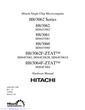
Hitachi H8/3064F-ZTAT Hardware Manual (939 pages)
Single-Chip Microcomputer
Brand:
Hitachi
| Category:
Computer Hardware
| Size: 2.98 MB
Table of Contents
Table of Contents
11
Section 1 Overview
26
Block Diagram
31
Pin Description
32
Pin Arrangement
32
Pin Functions
37
Pin Assignments in each Mode
41
Notes on H8/3062F-ZTAT R-Mask Version
45
Pin Arrangement
45
Product Type Names and Markings
46
Differences between H8/3062F-ZTAT and H8/3062F-ZTAT R-Mask Version
46
Notes on H8/3064F-ZTAT and H8/3062F-ZTAT A-Mask Version
47
Pin Arrangement
47
Product Type Names and Markings
48
Note on Changeover to Mask ROM Version
50
VCL Pin
50
Setting Oscillation Settling Wait Time
51
Caution on Crystal Resonator Connection
51
Cpu
52
Overview
52
Features
52
Differences from H8/300 CPU
53
CPU Operating Modes
53
Address Space
54
Register Configuration
55
Overview
55
2.4.2 General Registers
56
Control Registers
57
Initial CPU Register Values
58
Data Formats
59
General Register Data Formats
59
Memory Data Formats
60
Instruction Set
62
Instruction Set Overview
62
Instructions and Addressing Modes
63
Tables of Instructions Classified by Function
64
2.6.4 Basic Instruction Formats
73
Notes on Use of Bit Manipulation Instructions
74
Addressing Modes and Effective Address Calculation
76
Addressing Modes
76
Effective Address Calculation
78
Processing States
82
Overview
82
Program Execution State
82
Exception-Handling State
83
Exception Handling Operation
84
Bus-Released State
85
Reset State
85
Power-Down State
86
Basic Operational Timing
86
Overview
86
On-Chip Memory Access Timing
86
On-Chip Supporting Module Access Timing
87
Access to External Address Space
88
MCU Operating Modes
89
Overview
89
Operating Mode Selection
89
Register Configuration
90
Mode Control Register (MDCR)
90
System Control Register (SYSCR)
91
Operating Mode Descriptions
93
Mode 1
93
Mode 2
93
Mode 3
94
Mode 4
94
Mode 5
94
Mode 7
94
Pin Functions in each Operating Mode
95
Memory Map in each Operating Mode
96
Comparison of H8/3062 Series Memory Maps
96
Reserved Areas
97
Exception Handling
106
Overview
106
Exception Handling Types and Priority
106
Exception Handling Operation
106
Exception Vector Table
107
Reset
109
Reset Sequence
109
Interrupts after Reset
112
Interrupts
113
Trap Instruction
113
Stack Status after Exception Handling
114
Notes on Stack Usage
115
Overview
117
Interrupt Controller
117
Features
117
Block Diagram
118
Pin Configuration
119
Register Configuration
119
Register Descriptions
119
System Control Register (SYSCR)
119
Interrupt Priority Registers a and B (IPRA, IPRB)
120
IRQ Status Register (ISR)
125
IRQ Enable Register (IER)
126
IRQ Sense Control Register (ISCR)
127
Interrupt Sources
128
External Interrupts
128
Internal Interrupts
129
Interrupt Exception Handling Vector Table
129
Interrupt Operation
133
Interrupt Handling Process
133
Interrupt Exception Handling Sequence
138
Interrupt Response Time
139
Usage Notes
140
Contention between Interrupt and Interrupt-Disabling Instruction
140
Instructions that Inhibit Interrupts
141
Interrupts During EEPMOV Instruction Execution
141
Bus Controller
142
Overview
142
Features
142
Block Diagram
143
Pin Configuration
144
Register Configuration
145
Register Descriptions
145
Bus Width Control Register (ABWCR)
145
Access State Control Register (ASTCR)
146
Wait Control Registers H and L (WCRH, WCRL)
147
Bus Release Control Register (BRCR)
151
Bus Control Register (BCR)
152
Chip Select Control Register (CSCR)
154
Address Control Register (ADRCR)
155
Operation
156
Area Division
156
Bus Specifications
159
Memory Interfaces
160
Address Output Method
161
Basic Bus Interface
163
Overview
163
Data Size and Data Alignment
163
Valid Strobes
164
Memory Areas
165
Basic Bus Control Signal Timing
166
Wait Control
173
Idle Cycle
175
Operation
175
Pin States in Idle Cycle
177
Bus Arbiter
177
Operation
178
Register and Pin Input Timing
180
Register Write Timing
180
BREQ Pin Input Timing
181
I/O Ports
182
Overview
182
Port 1
186
Overview
186
Register Descriptions
186
Port 2
189
Overview
189
Register Descriptions
190
Port 3
193
Overview
195
Register Descriptions
199
Port 4
201
Overview
201
Port 5
201
Overview
205
Port 6
205
Port 7
205
Register Description
206
Port 8
207
Overview
207
Register Descriptions
213
Overview
217
Port a
217
Register Descriptions
219
Port B
229
Overview
229
Register Descriptions
231
16-Bit Timer
237
Overview
237
Features
237
Block Diagrams
239
Pin Configuration
242
Register Configuration
243
Register Descriptions
244
Timer Start Register (TSTR)
244
Timer Synchro Register (TSNC)
245
Timer Mode Register (TMDR)
246
Timer Interrupt Status Register a (TISRA)
249
Timer Interrupt Status Register B (TISRB)
251
Timer Interrupt Status Register C (TISRC)
254
Timer Counters (16TCNT)
256
General Registers (GRA, GRB)
257
Timer Control Registers (16TCR)
258
Timer I/O Control Register (TIOR)
260
Timer Output Level Setting Register C (TOLR)
262
CPU Interface
264
16-Bit Accessible Registers
264
8-Bit Accessible Registers
266
Operation
267
Overview
267
Basic Functions
267
Synchronization
275
PWM Mode
277
Phase Counting Mode
281
16-Bit Timer Output Timing
283
Interrupts
284
Setting of Status Flags
284
Timing of Clearing of Status Flags
286
Usage Notes
288
8-Bit Timers
300
Overview
300
Features
300
Block Diagram
302
Pin Configuration
303
Register Configuration
304
Register Descriptions
305
Timer Counters (8TCNT)
305
Time Constant Registers a (TCORA)
306
Time Constant Registers B (TCORB)
307
Timer Control Register (8TCR)
308
Timer Control/Status Registers (8TCSR)
311
CPU Interface
316
8-Bit Registers
316
Operation
318
8TCNT Count Timing
318
Compare Match Timing
319
Input Capture Signal Timing
320
Timing of Status Flag Setting
321
Operation with Cascaded Connection
322
Input Capture Setting
325
Interrupt
326
Interrupt Sources
326
A/D Converter Activation
327
8-Bit Timer Application Example
327
Usage Notes
328
Contention between 8TCNT Write and Clear
328
Contention between 8TCNT Write and Increment
329
Contention between TCOR Write and Compare Match
330
Contention between TCOR Read and Input Capture
331
Contention between Counter Clearing by Input Capture and Counter Increment
332
Contention between TCOR Write and Input Capture
333
Contention between 8TCNT Byte Write and Increment in 16-Bit Count Mode (Cascaded Connection)
334
Contention between Compare Matches a and B
335
8TCNT Operation and Internal Clock Source Switchover
335
Section 10 Programmable Timing Pattern Controller (TPC)
338
Overview
338
Features
338
Block Diagram
339
Pin Configuration
340
Register Configuration
341
Register Descriptions
342
Port a Data Direction Register (PADDR)
342
Port a Data Register (PADR)
342
Port B Data Direction Register (PBDDR)
343
Port B Data Register (PBDR)
343
Next Data Register a (NDRA)
344
Next Data Register B (NDRB)
346
Next Data Enable Register a (NDERA)
348
Next Data Enable Register B (NDERB)
349
TPC Output Control Register (TPCR)
350
TPC Output Mode Register (TPMR)
352
Operation
354
Overview
354
Output Timing
355
Normal TPC Output
356
Non-Overlapping TPC Output
358
TPC Output Triggering by Input Capture
360
Usage Notes
361
Operation of TPC Output Pins
361
Note on Non-Overlapping Output
361
Section 11 Watchdog Timer
363
Overview
363
Features
363
Block Diagram
364
Pin Configuration
364
Register Configuration
365
Register Descriptions
365
Timer Counter (TCNT)
365
Timer Control/Status Register (TCSR)
366
Reset Control/Status Register (RSTCSR)
368
Notes on Register Access
369
Operation
371
Watchdog Timer Operation
371
Timing of Setting of Overflow Flag (OVF)
372
Timing of Setting of Watchdog Timer Reset Bit (WRST)
373
Interrupts
374
Usage Notes
374
Section 12 Serial Communication Interface
375
Overview
375
Features
375
Block Diagram
377
Pin Configuration
378
Register Configuration
379
Register Descriptions
380
Receive Shift Register (RSR)
380
Receive Data Register (RDR)
380
Transmit Shift Register (TSR)
381
Transmit Data Register (TDR)
381
Serial Mode Register (SMR)
382
Serial Control Register (SCR)
385
Serial Status Register (SSR)
389
Bit Rate Register (BRR)
394
Operation
402
Overview
402
Operation in Asynchronous Mode
405
Multiprocessor Communication
414
Synchronous Operation
421
SCI Interrupts
429
Usage Notes
430
Notes on Use of SCI
430
Section 13 Smart Card Interface
435
Overview
435
Features
435
Block Diagram
436
Pin Configuration
436
Register Configuration
437
Register Descriptions
438
Smart Card Mode Register (SCMR)
438
Serial Status Register (SSR)
440
Serial Mode Register (SMR)
441
Serial Control Register (SCR)
442
Operation
443
Overview
443
Pin Connections
443
Data Format
444
Register Settings
446
Clock
448
Transmitting and Receiving Data
450
Usage Notes
457
Section 14 A/D Converter
460
Overview
460
Features
460
Block Diagram
461
Pin Configuration
462
Register Configuration
463
Register Descriptions
463
A/D Data Registers a to D (ADDRA to ADDRD)
463
A/D Control/Status Register (ADCSR)
464
A/D Control Register (ADCR)
466
CPU Interface
467
Operation
469
Single Mode (SCAN = 0)
469
Scan Mode (SCAN = 1)
471
Input Sampling and A/D Conversion Time
473
External Trigger Input Timing
474
Interrupts
475
Usage Notes
475
Section 15 D/A Converter
480
Overview
480
Features
480
Block Diagram
481
Pin Configuration
482
Register Configuration
482
Register Descriptions
483
D/A Data Registers 0 and 1 (DADR0, DADR1)
483
D/A Control Register (DACR)
483
D/A Standby Control Register (DASTCR)
485
Operation
485
D/A Output Control
487
Section 16 RAM
488
Overview
488
Block Diagram
489
Register Configuration
489
System Control Register (SYSCR)
490
Operation
491
Section 17 ROM
492
On-Chip Mask ROM Models]
492
Overview
492
Overview of Flash Memory (H8/3062F-ZTAT, H8/3062F-ZTAT R-Mask Version)
493
Features
493
Block Diagram
494
Pin Configuration
495
Register Configuration
495
Flash Memory Register Descriptions
496
Flash Memory Control Register (FLMCR)
496
Erase Block Register (EBR)
499
RAM Control Register (RAMCR)
546
On-Board Programming Mode
554
Boot Mode
555
User Program Mode
560
Flash Memory Programming/Erasing
562
Program Mode
564
Program-Verify Mode
565
Erase Mode
569
Erase-Verify Mode
569
Flash Memory Protection
571
Hardware Protection
571
Software Protection
572
Error Protection
572
NMI Input Disabling Conditions
577
Flash Memory PROM Mode
578
18.10.1 Socket Adapters and Memory Map
578
18.10.2 Notes on Use of PROM Mode
579
Flash Memory Programming and Erasing Precautions
579
Block Diagram
588
Section 18 Flash Memory [H8/3064F-ZTAT]
588
Pin Configuration
589
Register Configuration
589
Flash Memory Control Register 2 (FLMCR2)
593
RAM Control Register (RAMCR)
595
Overview of Operation
597
Mode Transitions
597
On-Board Programming Modes
599
Flash Memory Emulation in RAM
601
Block Configuration
602
On-Board Programming Mode
603
Boot Mode
604
User Program Mode
609
Flash Memory Programming/Erasing
611
Program Mode
613
Program-Verify Mode
614
Erase Mode
618
Erase-Verify Mode
618
Flash Memory Protection
620
Hardware Protection
620
Software Protection
621
Flash Memory Programming and Erasing Precautions
628
Notes When Converting the F-ZTAT Application Software to the Mask-ROM Versions
634
Section 20 Clock Pulse Generator
635
Overview
635
Block Diagram
635
Oscillator Circuit
636
Connecting a Crystal Resonator
636
External Clock Input
638
Duty Adjustment Circuit
640
Prescalers
640
Frequency Divider
640
Register Configuration
641
Division Control Register (DIVCR)
641
Usage Notes
642
Section 21 Power-Down State
643
Overview
643
Register Configuration
645
System Control Register (SYSCR)
645
Module Standby Control Register H (MSTCRH)
647
Module Standby Control Register L (MSTCRL)
648
Sleep Mode
650
Transition to Sleep Mode
650
Exit from Sleep Mode
650
Software Standby Mode
650
Transition to Software Standby Mode
650
Exit from Software Standby Mode
651
Selection of Waiting Time for Exit from Software Standby Mode
651
Sample Application of Software Standby Mode
653
Note
653
Cautions on Clearing the Software Standby Mode of F-ZTAT Version
654
Hardware Standby Mode
655
Transition to Hardware Standby Mode
655
Exit from Hardware Standby Mode
655
Timing for Hardware Standby Mode
655
Module Standby Function
656
Module Standby Timing
656
Read/Write in Module Standby
656
Usage Notes
656
System Clock Output Disabling Function
657
Section 22 Electrical Characteristics
658
Electrical Characteristics of H8/3062 Mask ROM Version, H8/3061 Mask ROM Version, and H8/3060 Mask ROM Version
660
Absolute Maximum Ratings
660
DC Characteristics
661
AC Characteristics
672
A/D Conversion Characteristics
678
D/A Conversion Characteristics
680
Electrical Characteristics of H8/3062F-ZTAT and H8/3062F-ZTAT R-Mask Version
681
Absolute Maximum Ratings
681
DC Characteristics
682
AC Characteristics
690
A/D Conversion Characteristics
696
D/A Conversion Characteristics
698
Flash Memory Characteristics
699
Electrical Characteristics of H8/3064F-ZTAT
703
Absolute Maximum Ratings
703
DC Characteristics
704
AC Characteristics
712
A/D Conversion Characteristics
718
D/A Conversion Characteristics
720
Flash Memory Characteristics
721
Electrical Characteristics of H8/3062F-ZTAT A-Mask Version
725
DC Characteristics
726
AC Characteristics
734
A/D Conversion Characteristics
740
D/A Conversion Characteristics
742
Flash Memory Characteristics
743
Operational Timing
747
Clock Timing
747
Control Signal Timing
748
Bus Timing
750
TPC and I/O Port Timing
754
Timer Input/Output Timing
754
SCI Input/Output Timing
755
Appendix A Instruction Set
756
Instruction List
756
Data Transfer Instructions
758
Arithmetic Instructions
760
Bit Manipulation Instructions
765
Operation Code Maps
771
Number of States Required for Execution
774
Appendix B Internal I/O Registers
783
Address List (H8/3062F-ZTAT, H8/3062F-ZTAT R-Mask Version, H8/3062 Mask ROM Version, H8/3061 Mask ROM Version, H8/3060 Mask ROM Version)
784
Address List (H8/3064F-ZTAT)
794
Address List (H8/3062F-ZTAT A-Mask Version)
804
Functions
814
Flash Memory
834
Appendix D Pin States
919
Port States in each Mode
919
Pin States at Reset
923
Appendix E Timing of Transition to and Recovery from Hardware Standby Mode
926
Appendix F Product Code Lineup
927
Appendix G Package Dimensions
929
Appendix H Comparison of H8/300H Series Product Specifications
932
Differences between H8/3067 and H8/3062 Series, H8/3048 Series, H8/3007 and H8/3006, and H8/3002
932
Comparison of Pin Functions of 100-Pin Package Products (FP-100B, TFP-100B)
935
Advertisement
Advertisement
Related Products
Hitachi H8/3062
Hitachi H8/3061
Hitachi H8/3062F-ZTAT
Hitachi H8/3060
Hitachi H8/3064B
Hitachi H8/3062B
Hitachi H8/3061B
Hitachi H8/3060B
Hitachi H8/3008
Hitachi H8/3034
Hitachi Categories
Projector
Air Conditioner
Drill
Power Tool
TV
More Hitachi Manuals
Login
Sign In
OR
Sign in with Facebook
Sign in with Google
Upload manual
Upload from disk
Upload from URL