Sign In
Upload
Manuals
Brands
Siemens Manuals
Relays
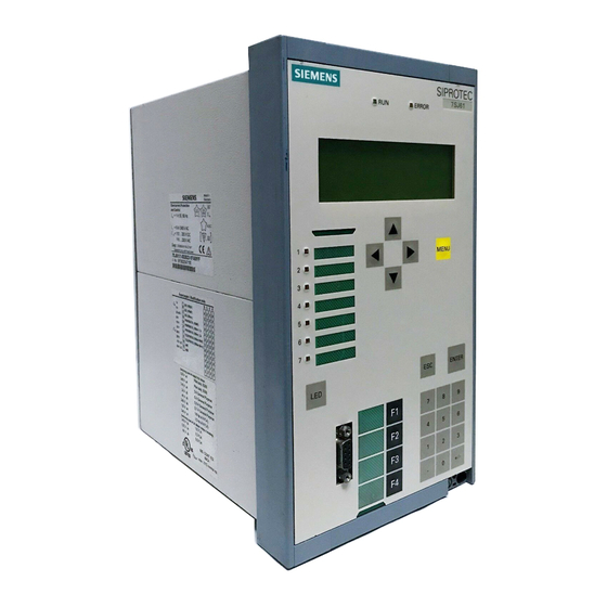
SIPROTEC 4 7SJ61
Siemens SIPROTEC 4 7SJ61 Manuals
Manuals and User Guides for Siemens SIPROTEC 4 7SJ61. We have
1
Siemens SIPROTEC 4 7SJ61 manual available for free PDF download: Manual
Siemens SIPROTEC 4 7SJ61 Manual (456 pages)
Multi-funktional Protective Relay with Bay Controller
Brand:
Siemens
| Category:
Relays
| Size: 14.51 MB
Table of Contents
Functions 3
3
Preface
3
Siprotec
4
7Sj61
5
C53000-G1140-C210
6
Table of Contents
9
1 Introduction
17
Overall Operation
18
Application Scope
20
Characteristics
22
2 Functions
27
General
28
Functional Scope
28
Description
28
Setting Notes
28
Settings
29
Device, General Settings
31
Command-Dependent Messages
31
Setting Notes
32
Settings
33
Information List
33
Power System Data 1
35
Description
35
Setting Notes
35
Settings
39
Information List
40
Oscillographic Fault Records
41
Description
41
Setting Notes
41
Settings
42
Information List
42
Settings Groups
42
Description
42
Setting Notes
43
Settings
43
Information List
43
Power System Data 2
43
Description
43
Setting Notes
44
Settings
44
Information List
44
EN100-Module
45
Description
45
Setting Notes
45
Information List
45
Overcurrent Protection 50, 51, 50N, 51N
46
General
46
Definite Time, High-Set Elements 50-3, 50-2, 50N-3, 50N-2
47
Definite Time Overcurrent Elements 50-1, 50N-1
49
Inverse Time Overcurrent Elements 51, 51N
52
Dynamic Cold Load Pickup Function
55
Inrush Restraint
55
Pickup Logic and Tripping Logic
57
Two-Phase Overcurrent Protection (Only Non-Directional)
58
Fast Busbar Protection Using Reverse Interlocking
59
Setting Notes
59
Settings
67
Information List
69
Dynamic Cold Load Pickup
72
Description
72
Setting Notes
74
Settings
75
Information List
76
Single-Phase Overcurrent Protection
77
Description
77
High-Impedance Ground Fault Unit Protection
78
Tank Leakage Protection
80
Setting Notes
81
Settings
86
Information List
86
Negative Sequence Protection 46
87
Definite Time Characteristic
87
Inverse Time Characteristic 46-TOC
88
Setting Notes
90
Settings
92
Information List
93
Motor Protection
94
Motor Starting Protection 48
94
Description
94
Setting Notes
97
Motor Restart Inhibit 66
98
Description
99
Setting Notes
103
Load Jam Protection (51M)
107
Description
107
Setting Notes
109
Motorprotection (Motor Starting Protection 48, Motor Restart Inhibit 66, Loadjam)
111
Settings
111
Information List
112
Thermal Overload Protection 49
113
Description
113
Setting Notes
115
Settings
119
Information List
120
Monitoring Functions
121
Measurement Supervision
121
General
121
Hardware Monitoring
121
Software Monitoring
123
Monitoring of the External Transformer Circuits
123
Setting Notes
124
Settings
125
Information List
125
Trip Circuit Supervision 74TC
126
Description
126
Setting Notes
128
Settings
129
Information List
129
Malfunction Responses of the Monitoring Functions
129
Description
129
Ground Fault Protection 64, 67N(S), 50N(S), 51N(S)
132
Current Elements 50Ns, 51Ns
132
Logic
132
Setting Notes
135
Settings
138
Information List
140
Intermittent Ground Fault Protection
141
Description
141
Setting Notes
144
Settings
145
Information List
145
Automatic Reclosing System 79
147
Program Execution
147
Blocking
150
Status Recognition and Monitoring of the Circuit Breaker
152
Controlling Protection Elements
153
Zone Sequencing / Fuse Saving Scheme
155
Setting Notes
156
Settings
161
Information List
165
Breaker Failure Protection 50BF
167
Description
167
Setting Notes
170
Settings
172
Information List
173
Flexible Protection Functions
174
Functional Description
174
Setting Notes
177
Settings
180
Information List
181
Temperature Detection Via RTD Boxes
182
Description
182
Setting Notes
183
Settings
184
Information List
188
Phase Rotation
190
Description
190
Setting Notes
190
Function Logic
191
Pickup Logic of the Entire Device
191
Tripping Logic of the Entire Device
191
Setting Notes
192
Auxiliary Functions
193
Message Processing
193
LED Displays and Binary Outputs (Output Relays)
193
Information on the Integrated Display (LCD) or Personal Computer
193
Information to a Substation Control Center
195
Statistics
195
Description
195
Circuit Breaker Maintenance
196
Motor Statistics
202
Setting Notes
203
Information List
204
Information List
205
Measurement
205
Display of Measured Values
206
Transfer of Measured Values
206
Information List
207
Average Measurements
208
Description
208
Setting Notes
208
Settings
208
Information List
208
Min/Max Measurement Setup
209
Description
209
Setting Notes
209
Settings
209
Information List
209
Set Points for Measured Values
210
Description
210
Setting Notes
210
Information List
211
Set Points for Statistic
211
Description
211
Setting Notes
211
Commissioning Aids
211
Description
212
Web Monitor
213
General
213
Functions
214
Operating Modes
215
Display Example
216
Setting Notes
217
Breaker Control
219
Control Device
219
Description
219
Information List
219
Types of Commands
220
Description
220
Command Sequence
220
Description
221
Interlocking
221
Command Logging
228
Description
228
3 Mounting and Commissioning
231
Mounting and Connections
232
Configuration Information
232
Hardware Modifications
235
General
235
Disassembly
237
Switch Elements on the Pcbs
239
Interface Modules
251
Reassembly
255
Installation
255
Panel Flush Mounting
255
Rack Mounting and Cubicle Mounting
257
Panel Flush Mounting
259
Checking Connections
260
Checking Data Connections of Interfaces
260
Checking the System Connections
262
Commissioning
265
Test Mode and Transmission Block
266
Testing the System Interface
266
Checking the Status of Binary Inputs and Outputs
267
Tests for Breaker Failure Protection
270
Testing User-Defined Functions
272
Current, and Phase Rotation Testing
272
Test for High Impedance Protection
272
Testing the Reverse Interlocking Scheme
273
Checking the Temperature Detection
273
Trip/Close Tests for the Configured Operating Devices
274
Creating Oscillographic Recordings for Tests
275
Final Preparation of the Device
276
4 Technical Data
279
General Device Data
280
Analog Inputs
280
Auxiliary Voltage
280
Binary Inputs and Outputs
281
Communication Interfaces
282
Electrical Tests
286
Mechanical Tests
287
Climatic Stress Tests
288
Service Conditions
289
Certifications
289
Design
289
Definite-Time Overcurrent Protection
290
Inverse-Time Overcurrent Protection
292
Inrush Restraint
302
Dynamic Cold Load Pickup
303
Single-Phase Overcurrent Protection
304
Negative Sequence Protection (Definite-Time Characteristic)
305
Negative Sequence Protection (Inverse-Time Characteristics)
306
Motor Starting Time Supervision
312
Motor Restart Inhibit
313
Load Jam Protection
314
Thermal Overload Protection
315
Ground Fault Detection (Sensitive/Insensitive)
317
Intermittent Ground Fault Protection
324
Automatic Reclosing
325
Breaker Failure Protection
326
Flexible Protection Functions
327
Temperature Detection
329
User-Defined Functions (CFC)
330
Auxiliary Functions
336
Switching Device Control
340
Dimensions
341
Panel Flush and Cubicle Mounting (Housing Size 1 / 3 )
341
Panel Flush and Cubicle Mounting (Housing Size )
341
Panel Flush Mounting and Cabinet Flush Mounting
342
Panel Flush Mounting and Cabinet Flush Mounting (Housing Size 1 / 2 )
342
Panel Surface Mounting
343
Panel Surface Mounting (Housing Size 1 / 3 )
343
Panel Surface Mounting (Housing Size 1 / 2 )
343
Varistor
344
A Ordering Information and Accessories
345
Ordering Information 7SJ61 V4.9
346
Accessories
349
B Terminal Assignments
351
Housing for Panel Flush and Cubicle Mounting
352
Housing for Panel Surface Mounting
355
Terminal Assignment on Housing for Panel Surface Mounting
358
Connector Assignment
360
B.4 Connector Assignment
360
C Connection Examples
361
Connection Examples for Current Transformers, All Devices
362
Connection Examples for RTD-Box, All Devices
367
D Current Transformer Requirements
369
Accuracy Limiting Factors
370
Class Conversion
371
D.2 Class Conversion
371
Cable Core Balance Current Transformer
372
Default Settings and Protocol-Dependent Functions
373
Leds
374
Binary Input
375
E.2 Binary Input
375
Binary Output
376
E.3 Binary Output
376
Function Keys
377
E.4 Function Keys
377
Default Display
378
E.5 Default Display
378
Pre-Defined CFC Charts
380
Protocol-Dependent Functions
381
F Functions, Settings, Information
383
Functional Scope
384
F.1 Functional Scope
384
Settings
386
F.2 Settings
386
Information List
406
F.3 Information List
406
Group Alarms
437
F.4 Group Alarms
437
Measured Values
438
F.5 Measured Values
438
Literature
441
Glossary
443
Index
453
Advertisement
Advertisement
Related Products
Siemens SIPROTEC 4 7SAJ8
Siemens SIPROTEC 4
Siemens SIPROTEC 7SD610
Siemens siprotec 7sj602
Siemens SIPROTEC 7SA511
Siemens siprotec 7SJ63
Siemens siprotec 7SD5
Siemens siprotec SJ62
Siemens siprotec SJ63
Siemens siprotec SJ64
Siemens Categories
Industrial Equipment
Controller
Control Unit
Oven
Washer
More Siemens Manuals
Login
Sign In
OR
Sign in with Facebook
Sign in with Google
Upload manual
Upload from disk
Upload from URL